JBL - 6010B - Amplifier
Manufacturer:
Image 1 of 1
If you have any other photos or manuals for the
JBL 6010B
you can
upload the files here.
Equipment:
6010B
Date:
Category:
Group:
Sub Group:
Information
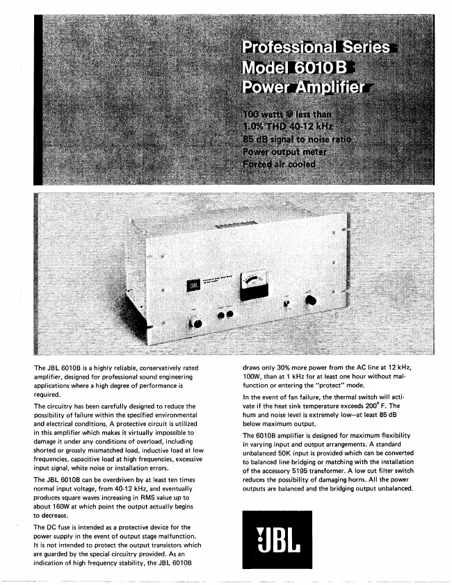
The JBL 6010B is a highly reliable, conservatively rated
amplifier, designed for professional sound engineering
applications where a high degree of performance is required.
The circuitry has been carefully designed to reduce the
possibility of failure within the specified environmental
and electrical conditions. A protective circuit is utilized
in this amplifier which makes it virtually impossible to
damage it under any conditions of overload, including
shorted or grossly mismatched load, inductive load at low
frequencies, capacitive load at high frequencies, excessive
input signal, white noise or installation errors.
The JBL 601 OB can be overdriven by at least ten times
normal input voltage, from 4(5-12 kHz, and eventually
produces square waves increasing in RMS value up to about
160W at which point the output actually begins to decrease.
The DC fuse is intended as a protective device for the power
supply in the event of output stage malfunction.
It is not intended to protect the output transistors which
are guarded by the special circuitry provided. As an
indication of high frequency stability, the JBL 601 OB
draws only 30% more power from the AC line at 12 kHz, 100W,
than at 1 kHz for at least one hour without malfunction or
entering the "protect" mode.
In the event of fan failure, the thermal switch will
activate if the heat sink temperature exceeds 200° F. The
hum and noise level is extremely low—at least 85 dB below
maximum output.
The 6010B amplifier is designed for maximum flexibility in
varying input and output arrangements. A standard unbalanced
50K input is provided which can be converted to balanced
line bridging or matching with the installation of the
accessory 5195 transformer. A low cut filter switch reduces
the possibility of damaging horns. All the power outputs are
balanced and the bridging output unbalanced.
1 Manual
Schematics diagram
Manual type:
Schematics diagram
Pages:
3
Size:
1.8 MB
Language:
english
Revision:
Manual-ID:
Date:
Quality:
Scanned document, reading partly badly, partly not readable.
Upload date:
Oct. 29, 2017
MD5:
0973229d-4f5d-eefb-af58-c9a38aa8245c
Downloads:
376