Wavetek - 907 - Generator
Manufacturer:
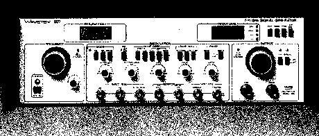
Image 1 of 1
If you have any other photos or manuals for the
Wavetek 907
you can
upload the files here.
Equipment:
907
Date:
1983
Category:
Group:
Sub Group:
Information
MODEL 907
The Model 907 Signal Generator is a lightweight, compact
source of RF signals. The 7 to 11 GHz frequency range is
continuously variable with front panel or external voltage
control; frequency is displayed on a 31/2 digit LCD. Output
level is continuously adjustable from 0 to -127 dBm by front
panel or external voltage control; a 3Vz digit LCD displays
the level. Modes of operation include CW, AM, FM and Pulse
with internal or external modulation and trigger signals. In
addition to the main RF output, there is a constant level
auxiliary output. Two sync outputs and two monitor outputs
allow timing and monitoring of modulation and triggering
functions.
1.2 SPECIFICATIONS
1.2.1 Versatility
The Mode! 907 Signal Generator is a signal source with AM,
FM, pulse modulation and external sweep capabilities. All
parameters are Independently adjustable.
Pulse and FM modulation signals may be externally provided
or selected from the Internal modulation generator.
Frequency and output level may also be externally (remotely)
controllable. External 0 to -I- 5V ramp with repetition
rates to 15 Hz will sweep the entire RF frequency range.
Internal modulator signals are available for monitoring and
system synchronization.
Modes
CW: Continuous RF output. Frequency and level adjustable.
FM: Internal or external signals can frequency modulate the
RF output. Rate and deviation are adjustable.
Pulse: internal or external signals can pulse modulate the
RF output. Pulse width adjustable or fixed 50% duty cycle;
rate and delay adjustable. External pulse mode can trigger
the pulse circuits on rising or falling edge of input
signal. A gate mode allows the external input to control
pulse width.
1.2.2 Output
NOTE
Output specifications applicable to nonswept operation only.
Frequency
Varied by a 10-turn potentiometer and a ± 4 MHz vernier or
by an external 0 to + 5V.
Range: 7.0 to 11.0 GHz.
Readout: 3 1/2 digit LCD, 10 MHz resolution.
Accuracy: ±1%of reading.
Stability: 60 ppm/°C; less than 20 ppm (± 10% line variation).
Signal Purity
(Internal frequency control, CW).
Residual FM: <15 kHz peak.
Harmonics: < -30 dBc
Spurious: < ~ 55 dBc
Level
Varied by a 10-turn potentiometer or external 0 to + 13.6V
(-10 dB/V). Output can be switched on and off.
Range (Leveled): 0 to -127 dBm; 0.225V to 0.100pN (into 50Ω).
Maximum Output: > + 3 dBm unleveled.
Readout: 3 1/" digit LCD, calibrated in dBref, dBm and Vrms.
Resolution: 0.1 dB.
Amplitude Accuracy:
Accuracy Output Level
±1dB 0 dBm
±2 dB 0 to — 60 dBm
±3dB -60 to -127 dBm
Below -127 dBm power decreases monotonically, but is
uncalibrated. Output level is continuously adjustable.
Impedance: 50Ω.
VSWR: <1.5
Connector: Female type N coax.
Auxiliary Output Power: > - 5 dBm CW signal. Reverse power
protection: + 30 dBm average.
1.2.3 Pulse Modulation
Transition Times: <35 ns for leading and trailing edges;
typically 12 ns/25 ns, respectively.
On-Off Ratio: > 80 dB when main output is set at 0 dBm.
Width: 200 ns to 100 (is in 2 ranges: for greater widths,
use external gated mode.
Delay Range: 3 to 1 ms in 2 ranges, relative to normal sync.
(Not applicable to gate mode.)
Internal Mode: Fixed square wave or variable width pulses;
10 Hz to 10 kHz in 3 ranges.
External Pulse Mode: Triggers internally generated pulse
delay and width from PULSE TRIG Input.
PULSE TRIG Input: 1 Vp-p minimum trigger; slope and trigger
point adjustable; ±10V maximum.
External Gate Mode: RF output occurs for the duration that
PULSE TRIG INPUT signal exceeds trigger level setting.
1.2.4 FM ■ Frequency Modulation
Maximum RF Output Deviation: >5 MHz p-p.
Internal Sawtooth Modulator: 10 Hz to 10 kHz in 3 ranges.
External FM Input: >1 MHz/V; ± 2.5V max level; 0 to >10 kHz;
10 kΩ input impedance.
1.2.5 AM • Amplitude Modulation
Ext. Modulation Frequency Range: 0 to 10 kHz.
Maximum Source Level: ± 2V peak.
Input Impedance: 10 kΩ.
Sensitivity: 27 dB/V (nominal).
1.2.6 Modulator Outputs
FM: Signal from external or internal modulation generator.
6000 source impedance.
Pulse: Positive TTL level pulse occurring at selected
repetition rate, pulse delay and pulse width of modulator pulse.
Normal Sync: Positive TTL level pulse occurring at selected
repetition rate.
Delayed Sync: Positive TTL level pulse synchronous with
modulator pulse with selected delay.
1 Manual
Service and user manual
Manual type:
Service and user manual
Pages:
89
Size:
3.2 MB
Language:
english
Revision:
K
Manual-ID:
Date:
January 1983
Quality:
Scanned document, all readable.
Upload date:
Aug. 15, 2018
MD5:
d16d3de5-c557-5e72-01f1-4d6bed1a1730
Downloads:
572