AVO - MK III - Valve characteristic meter
Manufacturer:
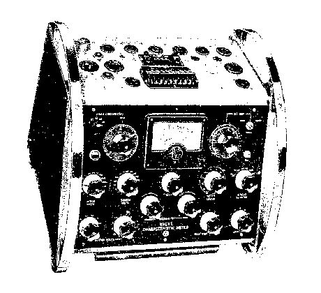
Image 1 of 1
If you have any other photos or manuals for the
AVO MK III
you can
upload the files here.
Equipment:
MK III
Date:
Category:
Group:
Sub Group:
Information
'The problem of designing a Valve Testing Instrument capable
of giving a true and comprehensive picture of the state of
any valve, has always been one of considerable magnitude,
increasing in complexity as new valve types are brought into
general use.
For a quick general purpose test necessitating a minimum of
time and technical effort a mutual conductance figure will
give an adequate idea of a valve’s usefulness, and the
original “ AVO ” Valve Tester was designed to test the
efficiency of valves on this basis.
Whilst a Valve Tester must, of necessity, be accompanied by
a data book correlating the results of the Tester with the
condition of the valve in question, a purely empirical
figure, if used as a standard, will always give rise to
doubts in the mind of the operator. The instrument should
therefore, produce a figure which can be compared with some
standard quoted by the valve manufacturer, if the operator
is to use his instrument with confidence. For this reason
the “ AVO ” Valve Tester used the static zero bias mutual
conductance figure as a basis of comparison, this figure
being at that time almost universally quoted by the valve
manufacturer.
In order to reproduce this standard correctly, it was also
necessary to reproduce the stated values of DC anode and
screen voltage, a matter of some considerable difficulty
when it is realised that for any stated condition of anode
and/or screen volts the corresponding electrode currents can
vary over very wide limits, and in the case of valves of low
initial anode current and high slope, the actuation of the
control which produces the milliamp-per-volt reading might
easily double the anode current flowing. With DC methods of
testing the inherent internal resistance of the rectifying
circuits used could be such as to give regulation errors
which could cause results to be meaningless unless
complicated thermionic stabilising circuits and a vast array
of monitoring meters were used in all voltage supply
circuits. Such complications would not only render the
Tester of prohibitive price and size, but would considerably
increase the complication of operation for the non-technical
user.
The problem was overcome by the introduction of the AC
method of operation (Patent No. 480752) by which means the
necessary DC test conditions were correctly simulated and a
true mutual conductance figure produced by the application
of AC voltages of suitable amplitude to all electrodes. This
enormously simplified the power supply problem, rendered
regulation errors negligible, and obviated the necessity for
voltage circuit monitoring. The “ AVO” Valve Tester thus
fulfilled normal testing needs for a longperiod.
During recent years, however, electronic techniques have
become much more precise and the nature and multiplicity of
valve types have continuously increased. The zero bias
mutual conductance figure is seldom quoted by the valve
manufacturers, who, usually now publish the optimum working
point mutual conductance and voltage figures, and in a large
number of cases give full families of curves, from which,
precise operation, under a variety of working conditions,
can be judged. To cater for present day requirements
therefore, a valve testing device should not only be capable
of producing a working point mutual conductance figure at
any reasonable value of anode, screen or grid voltage
recommended by the manufacturers, but should also be
capable, if necessary, or reproducing any one of the mutual
characteristics associated with the valve in question.
1 Manual
Service and user manual
Manual type:
Service and user manual
Pages:
28
Size:
1.6 MB
Language:
english
Revision:
Manual-ID:
Date:
Quality:
Scanned document, all readable.
Upload date:
May 9, 2014
MD5:
4e28d5c4-2866-22db-7b51-3db57f51eba8
Downloads:
2065