Acer - Aspire 1610 Series - Notebook
Manufacturer:
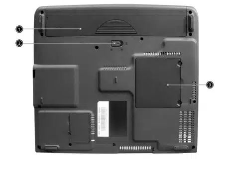
Image 1 of 4
If you have any other photos or manuals for the
Acer Aspire 1610 Series
you can
upload the files here.
Equipment:
Aspire 1610 Series
Date:
2004
Category:
Group:
Sub Group:
Information
Features
This computer was designed with the user in mind. Here are
just a few of its many features:
Performance
1 Manual
Service manual
Manual type:
Service manual
Pages:
136
Size:
4.4 MB
Language:
english
Revision:
Manual-ID:
Date:
Quality:
Electronic document, no scan, very well readable.
Upload date:
July 3, 2016
MD5:
4580cfe4-cfcd-8e2a-1e02-b4baad8b80c8
Downloads:
485