Advantest Corporation - TR 4120A - Oscilloscope
Manufacturer:
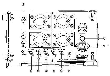
Image 1 of 2
If you have any other photos or manuals for the
Advantest Corporation TR 4120A
you can
upload the files here.
Equipment:
TR 4120A
Date:
1989
Category:
Group:
Sub Group:
Information
TR4120A is a tracking scope having the following performance:
100Hz to 30MHz Max. 10Hz Max. -135dBV 80dB
Measurement range Resolution Input sensitivity Dynamic range
Furthermore, since TR4120A includes a tracking generator, it
directly reads and analyzes the frequency characteristics in
addition to analyzing the spectrum. Also, connecting an
ADVANTEST frequency counter to this device provides a
function to read the frequency on the marker point at an
accuracy specified by the frequency counter.
This tracking generator is operated as a selective amplifier
(or tuned amplifier.) Using this function, some weak signal
is selected and amplified. The ON-AIR signal can be measured
at an accuracy specified by the carrier frequency counter.
1 Manual
User manual
Manual type:
User manual
Pages:
69
Size:
1.1 MB
Language:
english
Revision:
Manual-ID:
0EB00 9005
Date:
January 1989
Quality:
Scanned document, all readable.
Upload date:
Aug. 26, 2017
MD5:
483c9f61-7468-a07d-bfc6-36f3577c6a63
Downloads:
371