Ailtech - 7310 - Other
Manufacturer:
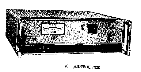
Image 1 of 5
If you have any other photos or manuals for the
Ailtech 7310
you can
upload the files here.
Equipment:
7310
Date:
1978
Category:
Group:
Sub Group:
Information
The System Noise Monitors described in this Instruction
Manual (7310 and 7320) are functionally identical. Each
provides a readout of the Noise Figure of a unit under
test (UUT) when connected in a valid measurement setup.
The minimum test setup consists of a SNM, the UUT, and a
solid state noise source of the AILTECH 7600 series.
The 7310 and 7320 have optional meter scales which
provide an Operating Noise Temperature readout in
lieu of Noise Figure.
The 7310 and 7320 SNM’s are referred to as analog
units because the readout is by a meter with two ranges.
Range selection is made by means of a front panel
switch. AILTECH also manufactures the 7360 and 7370
which indicate Noise Figure by means of a three-digit
LED display and are generally referred to as digital
units.
The 7310 is 7½ inches wide and is intended for bench-top
use while the 7320 is approximately 17 inches wide and is
intended for rack mounting. The optional Rack Mount Angle
Brackets (Option 11) must be attached for mounting
in a standard 19 inch rack.
2 Manuals
Service and user manual
Manual type:
Service and user manual
Pages:
48
Size:
1.4 MB
Language:
english
Revision:
B
Manual-ID:
Date:
Quality:
Scanned document, all readable.
Upload date:
March 16, 2013
MD5:
0b4f0635-a907-f9ba-1ca8-8e1ddd578fe3
Downloads:
1126
Service and user manual
Manual type:
Service and user manual
Pages:
102
Size:
3.5 MB
Language:
english
Revision:
Manual-ID:
Date:
Quality:
Scanned document, all readable.
Upload date:
April 22, 2014
MD5:
cba1429e-6844-dfbe-f00a-ccb0ffe62959
Downloads:
1119