Anritsu - MG3691A - Generator
Manufacturer:
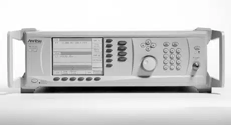
Image 1 of 2
If you have any other photos or manuals for the
Anritsu MG3691A
you can
upload the files here.
Equipment:
MG3691A
Date:
2005
Category:
Group:
Sub Group:
Information
The series MG369XA is a microprocessor-based, synthesized
signal source with high resolution phase-lock capability. It
generates both discrete CW frequencies and broad (full
range) and narrow band step sweeps across the frequency
range of 2 GHz to 65 GHz. Options are available to extend
the low end of the frequency range to 0.1 Hz. All
functions of the CW generator are fully controllable locally
from the front panel or remotely (except for power
on/standby) via the IEEE-488 General Purpose Interface Bus
(GPIB). Table 1-1 on page 1-4 lists models, frequency
ranges, and maximum leveled output power.
2 Manuals
Service manual
Manual type:
Service manual
Pages:
348
Size:
4.1 MB
Language:
english
Revision:
D
Manual-ID:
10370-10355
Date:
January 2005
Quality:
Electronic document, no scan, very well readable.
Upload date:
Oct. 15, 2017
MD5:
e7b0f485-f31d-35ac-1690-d6e67eff4c43
Downloads:
2605
User manual
Manual type:
User manual
Pages:
269
Size:
4.6 MB
Language:
english
Revision:
H
Manual-ID:
10370-10353
Date:
April 2005
Quality:
Electronic document, no scan, very well readable.
Upload date:
Oct. 15, 2017
MD5:
9d8c1c57-0982-9272-9a7a-dde2d17288ee
Downloads:
2241