Electro Scientific Industries - 253 - Level Meter
Manufacturer:
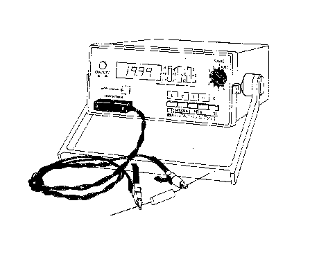
Image 1 of 1
If you have any other photos or manuals for the
Electro Scientific Industries 253
you can
upload the files here.
Equipment:
253
Date:
1979
Category:
Group:
Sub Group:
Information
The ESI Model 253 Digital Impedance Meter is a
semi-automatic instrument which permits rapid measurement of
inductance (L) , capacitance (C) , resistance (R) ,
conductance (G) , and dissipation factor (D) at a test
frequency of 1kHz. Measurement accuracy and versatility
satisfies most demanding engineering or scientific
applications .
This instrument has both an autoranging mode and a manual
range selection mode. The autoranging feature eliminates the
need for manual range selecting, thus saving time and
avoiding operator errors. It is designed to measure an
unknown and select the lowest corresponding range
automatically, thereby providing the highest resolution
display. When a series of measurements are to be made within
a particular range, time can be saved by turning the range
switch to the corresponding fixed range position. Front
panel LED lamps indicate the unit of measurement being
displayed by the 3-1/2 digit LED readout.
To operate, merely push the button for the desired function,
manually turn the knob to the desired range, and connect the
unknown. KELVIN KLIPS® test leads are included, thus
ensuring true four-terminal connections.
Excellent reliability of the Model 253 is assured through
use of solid state devices and etched circuit board
construction. Its small size is ideal for use on benchtops
where work space may be at a premium. The carrying handle
tilts the unit to a convenient viewing angle. Rear panel
brackets provide line cord storage and enable it to be
operated in a vertical position.
1 Manual
Service and user manual
Manual type:
Service and user manual

Pages:
78
Size:
2.1 MB
Language:
english
Revision:
Manual-ID:
43761B
Date:
June 1985
Quality:
Scanned document, reading partly badly, partly not readable.
Upload date:
Sept. 12, 2016
MD5:
c47cb799-81b7-8741-fce7-06230dddc50a
Downloads:
530