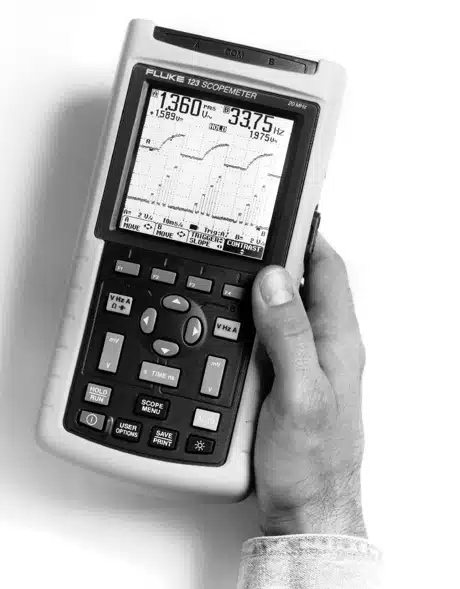
Fluke 123 ScopeMeter
Manufacturer:
Model:
123
Date:
unknown
Class:
Type:
SubType:
Information
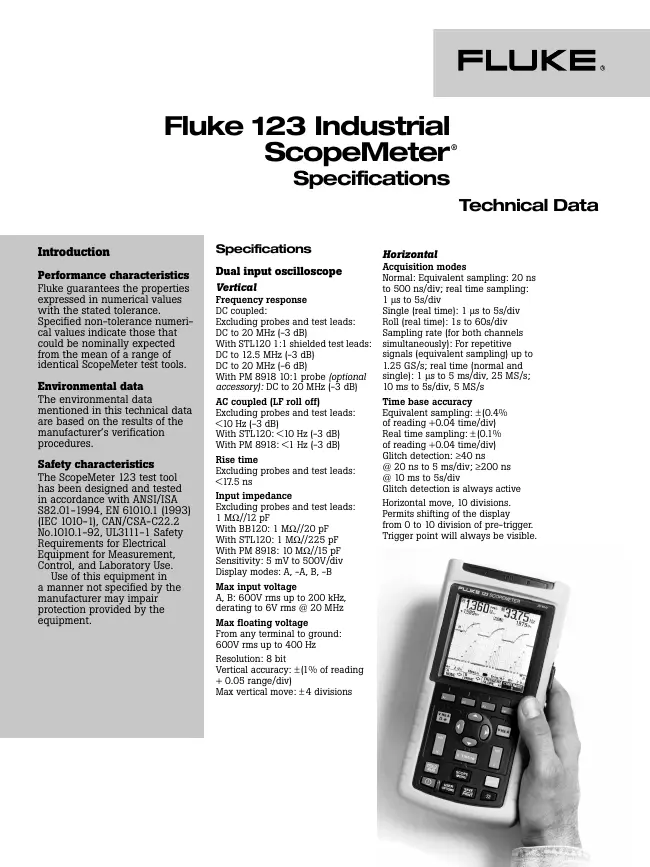
Dual input oscilloscope
Vertical
Frequency response
DC coupled:
Excluding probes and test leads:
DC to 20 MHz (-3 dB)
With STL120 1:1 shielded test leads:
DC to 12.5 MHz (-3 dB)
DC to 20 MHz (-6 dB)
With PM 8918 10:1
Probe (optional
accessory): DC to 20 MHz (-3 dB)
AC coupled (LF roll off)
Excluding probes and test leads:
<10 Hz (-3 dB)
With STL120: <10 Hz (-3 dB)
With PM 8918: <1 Hz (-3 dB)
Rise time
Excluding probes and test leads:
<17.5 ns
Input impedance
Excluding probes and test leads:
1 MW//12 pF
With BB120: 1 MW//20 pF
With STL120: 1 MW//225 pF
With PM 8918: 10 MW//15 pF
Sensitivity: 5 mV to 500V/div
Display modes: A, -A, B, -B
Max input voltage
A, B: 600V rms up to 200 kHz,
derating to 6V rms @ 20 MHz
Max floating voltage
From any terminal to ground:
600V rms up to 400 Hz
Resolution: 8 bit
Vertical accuracy: ±(1% of reading
+ 0.05 range/div)
Max vertical move: ±4 divisions
Horizontal
Acquisition modes
Normal: Equivalent sampling: 20 ns
to 500 ns/div; real time sampling:
1 ms to 5s/div
Single (real time): 1 ms to 5s/div
Roll (real time): 1s to 60s/div
Sampling rate (for both channels
simultaneously): For repetitive
signals (equivalent sampling) up to
1.25 GS/s; real time (normal and
single): 1 ms to 5 ms/div, 25 MS/s;
10 ms to 5s/div, 5 MS/s
Time base accuracy
Equivalent sampling: ±(0.4%
of reading +0.04 time/div)
Real time sampling: ±(0.1%
of reading +0.04 time/div)
Glitch detection: ³40 ns
@ 20 ns to 5 ms/div; ³200 ns
@ 10 ms to 5s/div
Glitch detection is always active
Horizontal move, 10 divisions.
Permits shifting of the display
from 0 to 10 division of pre-trigger.
Trigger point will always be visible.
Manual type:
Service Manual
Pages:
170
Size:
5.26 Mbytes (5519764 Bytes)
Language:
english
Revision:
3
Manual-ID:
4822 872 05375
Date:
unknown
Quality:
Electronic document, no scan, very well readable.
Upload date:
2014 11 29
MD5:
d1e4ef72a9bc1d3fa26a274826207797
Downloads:
874
Information
1 Safety Instructions
...
1-1
1.1
Introduction ...
1-3
1.2 Safety
Precautions ...
1-3
1.3 Caution and Warning
Statements ...
1-3
1.4
Symbols ...
1-3
1.5 Impaired Safety
...
1-4
1.6 General Safety
Information ...
1-4
2 Characteristics
...
2-1
2.1
Introduction ...
2-3
2.2 Dual Input
Oscilloscope ...
2-3
2.2.1 Vertical
...
2-3
2.2.2 Horizontal
...
2-4
2.2.3 Trigger
...
2-4
2.2.4 Advanced Scope
Functions ...
2-5
2.3 Dual Input
Meter ...
2-5
2.3.1 Input A and Input B
...
2-5
2.3.2 Input A
...
2-8
2.3.3 Advanced Meter
Functions ...
2-8
2.4 Miscellaneous
...
2-9
2.5 Environmental
...
2-10
2.6 Service and Maintenance
...
2-11
2.7 Safety
...
2-11
2.8 EMC Immunity
...
2-12
3 Circuit Descriptions
...
3-1
3.1
Introduction ...
3-3
3.2 Block Diagram
...
3-3
3.2.1 Channel A, Channel B Measurement
Circuits ... 3-4
3.2.2 Trigger Circuit
...
3-4
3.2.3 Digital Circuit
...
3-5
3.2.4 Power Circuit
...
3-6
3.2.5 Start-up Sequence, Operating Modes
... 3-7
3.3 Detailed Circuit
Descriptions ...
3-9
3.3.1 Power Circuit
...
3-9
3.3.2 Channel A - Channel B Measurement Circuits
... 3-15
3.3.3 Trigger Circuit
...
3-20
3.3.4 Digital Circuit
...
3-25
4 Performance
Verification ...
4-1
4.1
Introduction ...
4-3
4.2 Equipment Required For Verification
... 4-3
4.3 How To
Verify ...
4-3
4.4 Display and Backlight Test
...
4-4
4.5 Input A and Input B Tests
...
4-5
4.5.1 Input A and B Base Line Jump
Test ... 4-6
4.5.2 Input A Trigger Sensitivity Test
... 4-7
4.5.3 Input A Frequency Response Upper Transition Point
Test ... 4-8
4.5.4 Input A Frequency Measurement Accuracy Test
... 4-8
4.5.5 Input B Frequency Measurement Accuracy Test
... 4-9
4.5.6 Input B Frequency Response Upper Transition Point Test
... 4-10
4.5.7 Input B Trigger Sensitivity Test
... 4-10
4.5.8 Input A and B Trigger Level and Trigger Slope
Test ... 4-11
4.5.9 Input A and B DC Voltage Accuracy Test
... 4-14
4.5.10 Input A and B AC Voltage Accuracy Test
... 4-15
4.5.11 Input A and B AC Input Coupling
Test ... 4-16
4.5.12 Input A and B Volts Peak Measurements
Test ... 4-17
4.5.13 Input A and B Phase Measurements Test
... 4-18
4.5.14 Input A and B High Voltage AC/DC Accuracy
Test ... 4-19
4.5.15 Resistance Measurements
Test ...
4-20
4.5.16 Continuity Function Test
...
4-21
4.5.17 Diode Test Function Test
...
4-22
4.5.18 Capacitance Measurements Test
... 4-22
4.5.19 Video Trigger
Test ...
4-23
5 Calibration Adjustment
...
5-1
5.1 General
...
5-3
5.1.1
Introduction ...
5-3
5.1.2 Calibration number and
date ...
5-3
5.1.3 General
Instructions ...
5-3
5.2 Equipment Required For
Calibration ...
5-4
5.3 Starting Calibration Adjustment
...
5-4
5.4 Contrast Calibration Adjustment
...
5-6
5.5 Warming Up & Pre-Calibration
...
5-7
5.6 Final Calibration
...
5-7
5.6.1 HF Gain Input A&B
...
5-7
5.6.2
Delta T Gain, Trigger Delay Time & Pulse Adjust Input
A ... 5-9
5.6.3 Pulse Adjust Input A (firmware V01.00 only)
... 5-10
5.6.4 Pulse Adjust Input
B ...
5-11
5.6.5 Gain DMM (Gain
Volt) ...
5-11
5.6.6 Volt
Zero ...
5-13
5.6.7 Zero Ohm (firmware V01.00
only) ... 5-13
5.6.8 Gain
Ohm ...
5-14
5.6.9 Capacitance Gain Low and
High ... 5-15
5.6.10 Capacitance Clamp &
Zero ...
5-15
5.6.11 Capacitance
Gain ...
5-16
5.7 Save Calibration Data and
Exit ...
5-16
6 Disassembling the Test Tool
... 6-1
6.1.
Introduction ...
6-3
6.2. Disassembling Procedures
...
6-3
6.1.1 Required Tools
...
6-3
6.2.2 Removing the Battery Pack
...
6-3
6.2.3 Removing the Bail
...
6-3
6.2.4 Opening the Test Tool
...
6-3
6.2.5 Removing the Main PCA
Unit ...
6-5
6.2.6 Removing the Display
Assembly ...
6-6
6.2.7 Removing the Keypad and Keypad
Foil ... 6-6
6.3 Disassembling the Main PCA
Unit ...
6-6
6.4 Reassembling the Main PCA Unit
...
6-8
6.5 Reassembling the Test
Tool ...
6-8
7 Corrective Maintenance
...
7-1
7.1
Introduction ...
7-3
7.2 Starting Fault Finding.
...
7-4
7.3 Charger
Circuit ...
7-4
7.4 Starting with a Dead Test Tool
...
7-6
7.4.1 Test Tool Completely
Dead ...
7-6
7.4.2 Test Tool
Software Does not Run.
... 7-7
7.4.3
Software Runs, Test Tool not Operative
... 7-7
7.5 Miscellaneous
Functions ...
7-8
7.5.1 Display and Back Light
...
7-8
7.5.2 Fly Back
Converter ...
7-9
7.5.3 Slow
ADC ...
7-10
7.5.4
Keyboard ...
7-11
7.5.5 Optical Port (Serial RS232
Interface) ...
7-11
7.5.6 Channel A, Channel B Voltage Measurements
... 7-12
7.5.7 Channel A Ohms and Capacitance
Measurements ... 7-13
7.5.8 Trigger
Functions ...
7-14
7.5.9 Reference
Voltages ...
7-15
7.5.10 Buzzer
Circuit ...
7-15
7.5.11 Reset ROM Circuit (PCB version <8
only) ... 7-16
7.5.12 RAM Test
...
7-16
7.5.13 Power
ON/OFF ...
7-16
7.5.14 PWM
Circuit ...
7-17
7.5.15 Randomize Circuit
...
7-17
7.6 Loading
Software ...
7-17
8 List of Replaceable
Parts ...
8-1
8.1
Introduction ...
8-3
8.2 How to Obtain
Parts ...
8-3
8.3 Final Assembly Parts
...
8-4
8.4 Main PCA Unit Parts
...
8-6
8.5 Main PCA Parts
...
8-7
8.6 Accessory Replacement Parts
...
8-24
8.7 Service
Tools ...
8-24
9 Circuit
Diagrams ...
9-1
9.1
Introduction ...
9-3
9.2 Schematic
Diagrams ...
9-4
10 Modifications
...
10-1
10.1
Software modifications
...
10-1
10.2 Hardware
modifications ...
10-1
Manual type:
Service Manual
Pages:
96
Size:
1.99 Mbytes (2082892 Bytes)
Language:
english
Revision:
Manual-ID:
4822 872 05398
Date:
unknown
Quality:
Electronic document, no scan, very well readable.
Upload date:
2014 11 29
MD5:
c87ad484e83e45f4a08037ec9a5bb2fb
Downloads:
1756
Information
Limited Warranty & Limitation of
Liability ...
ii
Introduction and Safety
Instructions ... 1-1
1.1 Introduction to Service Manual
...
1-3
1.2 Safety
...
1-3
1.2.1
Introduction ...
1-3
1.2.2 Safety
Precautions ...
1-3
1.2.3 Caution and Warning
Statements ...
1-3
1.2.4 Symbols used in this Manual and on Instrument
... 1-4
1.2.5 Impaired
Safety ...
1-4
1.2.6 General Safety
Information ...
1-4
Characteristics
... 2-1
2.1
Introduction ...
2-3
2.2 Dual Input
Oscilloscope ...
2-3
2.2.1
Vertical ...
2-3
2.2.2 Horizontal
...
2-4
2.2.3 Trigger
...
2-4
2.2.4 Advanced Scope
Functions ...
2-5
2.3 Dual Input
Meter ...
2-5
2.3.1 Input A and Input B
...
2-5
2.3.2 Input A
...
2-8
2.3.3 Advanced Meter Functions
...
2-9
2.4 Cursor Readout (Fluke 124,
125) ...
2-10
2.5 Harmonics Measurements (Fluke
125) ...
2-10
2.6 Field Bus Measurements (Fluke 125)
...
2-11
2.7 Miscellaneous
...
2-11
2.8
Environmental ...
2-12
2.9 Service and Maintenance
...
2-13
2.10 Safety
...
2-13
2.11 EMC Immunity
...
2-15
Performance
Verification ... 3-1
3.1
Introduction ...
3-3
3.2 Equipment Required For Verification
... 3-3
3.3 How To
Verify ...
3-4
3.4 Display and Backlight
Test ...
3-4
3.5 Input A and Input B
Tests ...
3-5
3.5.1 Input A and B Base Line Jump Test
... 3-6
3.5.2 Input A Trigger Sensitivity Test
...
3-8
3.5.3 Input A Frequency Response Upper Transition Point Test
... 3-9
3.5.4 Input A Frequency Measurement Accuracy Test
... 3-9
3.5.5 Input B Frequency Measurement Accuracy
Test ... 3-10
3.5.6 Input B Frequency Response Upper Transition Point
Test ... 3-11
3.5.7 Input B Trigger Sensitivity Test
...
3-12
3.5.8 Input A and B Trigger Level and Trigger Slope Test
... 3-13
3.5.9 Input A and B DC Voltage Accuracy Test
... 3-16
3.5.10 Input A and B AC Voltage Accuracy Test
... 3-18
3.5.11 Input A and B AC Input Coupling Test
... 3-19
3.5.12 Input A and B Volts Peak Measurements Test
... 3-20
3.5.13 Input A and B Phase Measurements Test
... 3-21
3.5.14 Harmonics (Fluke 125)
...
3-21
3.5.15 Input A and B High Voltage AC/DC Accuracy
Test ... 3-22
3.5.16 Resistance Measurements Test
...
3-24
3.5.17 Continuity Function Test
...
3-25
3.5.18 Diode Test Function
Test ...
3-26
3.5.19 Capacitance Measurements
Test ...
3-26
3.5.20 Video Trigger
Test ...
3-27
Calibration
Adjustment ... 4-1
4.1
General ...
4-3
4.1.1
Introduction ...
4-3
4.1.2 Calibration number and
date ...
4-3
4.1.3 General
Instructions ...
4-3
4.2 Equipment Required For
Calibration ...
4-4
4.3 Starting Calibration Adjustment
...
4-4
4.4 Contrast Calibration Adjustment
...
4-6
4.5 Warming Up &
Pre-Calibration ...
4-7
4.6 Final Calibration
...
4-7
4.6.1 HF Gain Input A&B
...
4-7
4.6.2
Delta T Gain, Trigger Delay Time & Pulse Adjust Input
A ... 4-9
4.6.3 Pulse Adjust Input B
...
4-10
4.6.4 Gain DMM (Gain Volt)
...
4-10
4.6.5 Volt
Zero ...
4-12
4.6.6 Zero
Ohm ...
4-12
4.6.7 Gain
Ohm ...
4-13
4.6.8 Capacitance Gain Low and High
...
4-14
4.6.9 Capacitance Clamp &
Zero ...
4-14
4.6.10 Capacitance Gain
...
4-15
4.7 Save Calibration Data and
Exit ...
4-15
Disassembling the Test Tool
... 5-1
5.1.
Introduction ...
5-3
5.2. Disassembling Procedures
...
5-3
5.1.1 Required
Tools ...
5-3
5.2.2 Removing the Battery Pack
...
5-3
5.2.3 Removing the Bail
...
5-3
5.2.4 Opening the Test Tool
...
5-3
5.2.5 Removing the Main PCA
Unit ...
5-5
5.2.6 Removing the Display
Assembly ...
5-6
5.2.7 Removing the Keypad and Keypad Foil
... 5-6
5.3 Disassembling the Main PCA
Unit ...
5-6
5.4 Reassembling the Main PCA
Unit ...
5-8
5.5 Reassembling the Test
Tool ...
5-8
List of Replaceable Parts
... 6-1
6.1
Introduction ...
6-3
6.2 How to Obtain
Parts ...
6-3
6.3 Service Centers
...
6-3
6.4 Final Assembly Parts
...
6-4
6.5 Main PCA Unit Parts
...
6-6
6.6 Service Tools
...
6-7
Manual type:
Datasheet
Pages:
4
Size:
729.75 Kbytes (747266 Bytes)
Language:
english
Revision:
A
Manual-ID:
J0661
Date:
unknown
Quality:
Electronic document, no scan, very well readable.
Upload date:
2014 11 30
MD5:
7d2cac54627692048572f02481b27222
Downloads:
656
Manual type:
User Manual
Pages:
83
Size:
1.84 Mbytes (1933945 Bytes)
Language:
english
Revision:
Manual-ID:
Date:
unknown
Quality:
Electronic document, no scan, very well readable.
Upload date:
2016 01 26
MD5:
06bfdf8754072d733a7d08576f198abd
Downloads:
1042
Information
Declaration of Conformity
...
1
Unpacking the Test Tool Kit
...
2
Safely Using the Test Tool
...
4
1 Using The Test
Tool ...
7
Goal of this Chapter
...
7
Powering the Test Tool
...
7
Resetting the Test Tool
...
8
Changing Backlight
...
9
Reading the Screen
...
10
Making Selections in a Menu
...
11
Looking at the Measurement
Connections ...
12
Displaying an Unknown Signal with Connect-and View™
... 13
Making
Measurements ...
14
Freezing the
Screen ...
16
Holding a Stable Reading
...
16
Making Relative
Measurements ...
17
Selecting Auto/Manual
Ranges ...
18
Changing the Graphic Representation on the Screen
... 18
TrendPlotting a Waveform
...
22
Acquiring the Waveform
...
23
Triggering on a Waveform
...
27
Saving and Recalling a Setup and a Screen
...
32
Making Cursor
Measurements ...
35
Using the 10:1
Probe for High Frequency
Measurements ... 38
Using a Printer
...
39
Using FlukeView®
Software
...
41
2 Maintaining the Test
Tool ...
43
About this Chapter
...
43
Cleaning the Test
Tool ...
43
Storing the Test
Tool ...
43
Charging the Rechargeable Battery
Pack ...
44
Keeping Batteries in Optimal Condition
...
45
Replacing and Disposing of the Rechargeable Battery Pack
... 46
Using and Adjusting 10:1 Scope Probes
...
47
Calibrating the Test
Tool ...
49
Parts and
Accessories
...
49
3 Tips and
Troubleshooting ...
53
Goal of this Chapter
...
53
Using the Tilt
Stand ...
53
Resetting the Test Tool
...
54
Changing the Information
Language ...
54
Changing the
Display ...
55
Changing Date and Time
...
56
Saving Battery Life
...
57
Changing the Auto Set
Options ...
58
Using Proper Grounding
...
59
Solving Printing and Other Communication Errors
... 60
Battery Testing of
Fluke
Accessories ...
60
4
Specifications ...
61
Introduction
...
61
Dual Input
Oscilloscope
...
62
Dual Input
Meter ...
65
Cursor readout (Fluke 124)
...
68
Miscellaneous
...
69
Environmental
...
70
Safety
...
70
Manual type:
Service Manual
Pages:
77
Size:
1.62 Mbytes (1697807 Bytes)
Language:
english
Revision:
4
Manual-ID:
4822 872 00743
Date:
unknown
Quality:
Electronic document, no scan, very well readable.
Upload date:
2016 01 26
MD5:
39798c0a31354b1504bed94ce32f6d3c
Downloads:
673
Information
Declaration of Conformity
...
1
Unpacking the Test Tool Kit
...
2
Safely Using the Test Tool
...
4
1 Using The Test Tool
...
7
Goal of this
Chapter ...
7
Powering the Test
Tool ...
7
Resetting the Test Tool
...
8
Changing
Backlight ...
9
Reading the
Screen ...
10
Making Selections in a
Menu ...
11
Looking at the Measurement Connections
...
12
Input A
...
12
Input B
...
12
COM
...
12
Displaying an Unknown Signal with Connect-and-View™
... 13
Making Measurements
...
14
Freezing the Screen
...
16
Holding a Stable Reading
...
16
Making Relative Measurements
...
17
Selecting Auto/Manual Ranges
...
18
Changing the Graphic Representation on the Screen
... 18
Changing the Amplitude
...
18
Changing the Time Base
...
18
Positioning the Waveform on the Screen
...
19
Smoothing the Waveform
...
20
Displaying the Envelope of a Waveform
...
21
TrendPlotting a
Waveform ...
22
Starting a TrendPlot™ function
...
22
Changing the TrendPlot Reading
...
23
Turning Off the TrendPlot Display
...
23
Acquiring the Waveform
...
23
Making a Single
Acquisition ...
23
Recording Slow Signals over a Long Period of Time
... 25
Selecting AC-Coupling
...
26
Reversing the Polarity of the Displayed Waveform
... 26
Triggering on a Waveform
...
27
Setting Trigger Level and Slope
...
27
Selecting the Trigger Parameters
...
28
Isolated
Triggering ...
29
Triggering on Video Signals
...
29
Triggering on a Specific Video Line
...
31
Saving and Recalling a Setup or a Screen
...
32
Saving
Screens ...
32
Recalling
Screens ...
33
Deleting Screens
...
33
Using a
Printer ...
34
Using FlukeView®
Software
...
36
2 Maintaining the Test Tool
...
37
About this
Chapter ...
37
Cleaning the Test Tool
...
37
Storing the Test Tool
...
37
Charging the Ni-Cd Battery Pack
...
38
Keeping Batteries in Optimal Condition
...
39
Replacing and Disposing of the Ni-Cd Battery Pack
... 40
Using and Adjusting 10:1 Scope Probes
...
41
Calibrating the Test Tool
...
43
Parts and
Accessories ...
43
Service Manual
...
43
Standard
Accessories ...
43
Optional
Accessories
...
46
3 Tips and Troubleshooting
...
47
Goal of this
Chapter ...
47
Using the Tilt Stand
...
47
Resetting the Test Tool
...
48
Changing the Information Language
...
48
Changing the Display
...
49
Adjusting the Screen Contrast
...
49
Setting the Grid Display
...
49
Changing Date and Time
...
50
Saving Battery Life
...
51
Setting the Power Down Timer
...
51
Changing the Auto Set Options
...
52
Using Proper
Grounding ...
53
Solving Printing and Other Communication Errors
... 54
4 Specifications
...
55
Introduction
...
55
Dual Input
Oscilloscope ...
56
Vertical ...
56
Horizontal
...
57
Trigger
...
57
Advanced Scope Functions
...
58
Dual Input
Meter ...
59
Input A and Input
B ...
59
Input A
...
60
Advanced Meter Functions
...
61
Miscellaneous ...
62
Environmental
...
63
Safety
...
64
Manual type:
Service Manual
Pages:
174
Size:
7.12 Mbytes (7464388 Bytes)
Language:
english
Revision:
Manual-ID:
4822 872 05389
Date:
2003 02 01
Quality:
Scanned document, all readable.
Upload date:
2020 07 22
MD5:
798e05075681c736483ff7a88df7f5da
Downloads:
511
Information
Safety Instructions ... 1-1
1.1 Introduction ... 1-3
1.2 Safety Precautions ... 1-3
1.3 Caution and Warning Statements ... 1-3
1.4 Symbols used in this Manual and on Instrument ... 1-3
1.5 Impaired Safety ... 1-4
1.6 General Safety Information ... 1-4
Characteristics ... 2-1
2.1 Introduction ... 2-3
2.2 Dual Input
Oscilloscope ... 2-3
2.2.1 Vertical ... 2-3
2.2.2 Horizontal ... 2-4
2.2.3 Trigger ... 2-4
2.2.4 Advanced Scope Functions ... 2-5
2.3 Dual Input Meter ... 2-5
2.3.1 Input A and Input B ... 2-5
2.3.2 Input A ... 2-8
2.3.3 Advanced Meter Functions ... 2-9
2.4 Cursor Readout (Fluke 124) ... 2-9
2.5 Miscellaneous ... 2-9
2.6 Environmental ... 2-11
2.7 Service and Maintenance ... 2-12
2.8 Safety ... 2-12
2.9 EMC Immunity ... 2-14
Circuit Descriptions ... 3-1
3.1 Introduction ... 3-3
3.2 Block Diagram ... 3-3
3.2.1 Channel A, Channel B Measurement Circuits ... 3-4
3.2.2 Trigger Circuit ... 3-4
3.2.3 Digital Circuit ... 3-5
3.2.4 Power Circuit ... 3-6
3.2.5 Start-up Sequence, Operating Modes ... 3-7
3.3 Detailed Circuit Descriptions ... 3-9
3.3.1 Power Circuit ... 3-9
3.3.2 Channel A - Channel B Measurement Circuits ... 3-15
3.3.3 Trigger Circuit ... 3-20
3.3.4 Digital Circuit and ADC’s ... 3-25
Performance Verification ... 4-1
4.1 Introduction ... 4-3
4.2 Equipment Required For Verification ... 4-3
4.3 How To Verify ... 4-3
4.4 Display and Backlight Test ... 4-4
4.5 Input A and Input B Tests ... 4-5
4.5.1 Input A and B Base Line Jump Test ... 4-6
4.5.2 Input A Trigger Sensitivity Test ... 4-7
4.5.3 Input A Frequency Response Upper Transition Point Test ... 4-8
4.5.4 Input A Frequency Measurement Accuracy Test ... 4-9
4.5.5 Input B Frequency Measurement Accuracy Test ... 4-10
4.5.6 Input B Frequency Response Upper Transition Point Test ... 4-10
4.5.7 Input B Trigger Sensitivity Test ... 4-11
4.5.8 Input A and B Trigger Level and Trigger Slope Test ... 4-12
4.5.9 Input A and B DC Voltage Accuracy Test ... 4-14
4.5.10 Input A and B AC Voltage Accuracy Test ... 4-16
4.5.11 Input A and B AC Input Coupling Test ... 4-17
4.5.12 Input A and B Volts Peak Measurements Test ... 4-18
4.5.13 Input A and B Phase Measurements Test ... 4-19
4.5.14 Input A and B High Voltage AC/DC Accuracy Test ... 4-20
4.5.15 Resistance Measurements Test ... 4-21
4.5.16 Continuity Function Test ... 4-22
4.5.17 Diode Test Function Test ... 4-23
4.5.18 Capacitance Measurements Test ... 4-23
4.5.19 Video Trigger Test ... 4-24
Calibration Adjustment ... 5-1
5.1 General ... 5-3
5.1.1 Introduction ... 5-3
5.1.2 Calibration number and date ... 5-3
5.1.3 General Instructions ... 5-3
5.2 Equipment Required For Calibration ... 5-4
5.3 Starting Calibration Adjustment ... 5-4
5.4 Contrast Calibration Adjustment ... 5-6
5.5 Warming Up & Pre-Calibration ... 5-7
5.6 Final Calibration ... 5-7
5.6.1 HF Gain Input A&B ... 5-7
5.6.2
Delta T Gain, Trigger Delay Time & Pulse Adjust Input A ... 5-9
5.6.3 Pulse Adjust Input B ... 5-10
5.6.4 Gain DMM (Gain Volt) ... 5-10
5.6.5 Volt Zero ... 5-12
5.6.6 Zero Ohm ... 5-12
5.6.7 Gain Ohm ... 5-13
5.6.8 Capacitance Gain Low and High ... 5-14
5.6.9 Capacitance Clamp & Zero ... 5-14
5.6.10 Capacitance Gain ... 5-15
5.7 Save Calibration Data and Exit ... 5-15
Disassembling the Test Tool ... 6-1
6.1. Introduction ... 6-3
6.2. Disassembling Procedures ... 6-3
6.1.1 Required Tools ... 6-3
6.2.2 Removing the Battery Pack ... 6-3
6.2.3 Removing the Bail ... 6-3
6.2.4 Opening the Test Tool ... 6-3
6.2.5 Removing the Main PCA Unit ... 6-5
6.2.6 Removing the Display Assembly ... 6-6
6.2.7 Removing the Keypad and Keypad Foil ... 6-6
6.3 Disassembling the Main PCA Unit ... 6-6
6.4 Reassembling the Main PCA Unit ... 6-8
6.5 Reassembling the Test Tool ... 6-8
Corrective Maintenance ... 7-1
7.1 Introduction ... 7-3
7.2 Starting Fault Finding. ... 7-4
7.3 Charger Circuit ... 7-4
7.4 Starting with a Dead Test Tool ... 7-6
7.4.1 Test Tool Completely Dead ... 7-6
7.4.2 Test Tool
Software Does not Run. ... 7-7
7.4.3
Software Runs, Test Tool not Operative ... 7-7
7.5 Miscellaneous Functions ... 7-8
7.5.1 Display and Back Light ... 7-8
7.5.2 Fly Back
Converter ... 7-9
7.5.3 Slow ADC ... 7-10
7.5.4 Keyboard ... 7-11
7.5.5 Optical Port (Serial RS232 Interface) ... 7-11
7.5.6 Channel A, Channel B Voltage easurements ... 7-11
7.5.7 Channel A Ohms and Capacitance Measurements ... 7-13
7.5.8 Trigger Functions ... 7-14
7.5.9 Reference Voltages ... 7-15
7.5.10 Buzzer Circuit ... 7-15
7.5.11 Reset ROM Circuit ... 7-16
7.5.12 RAM Test ... 7-16
7.5.13 Power ON/OFF ... 7-17
7.5.14 PWM Circuit ... 7-17
7.5.15 Randomize Circuit ... 7-17
7.6 Loading
Software ... 7-17
7.7 Configuration of CPLD-chip D470 ... 7-17
Circuit Diagrams ... 9-1
9.1 Introduction ... 9-1
9.2 Schematic Diagrams ... 9-2
Modifications ... 10-1
10.1
Software modifications ... 10-1
10.2 Hardware modifications ... 10-1
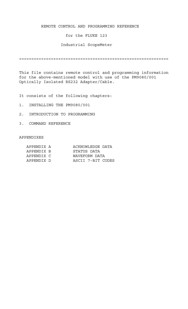
Manual type:
User Manual
Pages:
98
Size:
118.98 Kbytes (121835 Bytes)
Language:
english
Revision:
Manual-ID:
Date:
unknown
Quality:
Electronic document, no scan, very well readable.
Upload date:
2023 03 20
MD5:
a339c682aa67a35f8c3b6ea3874aa0a7
Downloads:
30
Comments