Fluke - 7250A - Counter
Manufacturer:
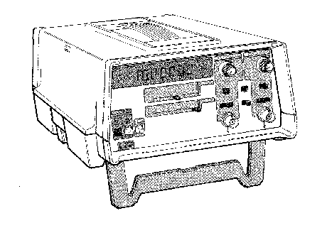
Image 1 of 1
If you have any other photos or manuals for the
Fluke 7250A
you can
upload the files here.
Equipment:
7250A
Date:
1978
Category:
Group:
Sub Group:
Information
1-2. The Model 7250A is a Universal Counter-Timer capable of
measurements in seven modes of operation: frequency (Channel
A, 5 Hz to 80 MHz), period and period averaging (Channel A,
5 Hz to 1 MHz), time interval (Channel A to Channel B, 5 Hz
to 2 MHz), counts per minute (Channel A, 5 Hz to 80 MHz),
ratio of Channel A (5 Hz to 80 MHz) divided by Channel B(5
Hz to 1 MHz), and totalize Channel A (5 Hz to 80 MHz). In
addition, Self Check mode is-provided to demonstrate
operability of most 7250A circuits.
1-3. This manual documents the 7250A Universal Counter-Timer
under two categories. The standard instrument without
options and accessories is covered in Sections 1 through 5,
7 and 8. All optional or accessory items are documented in
Section 6; refer to Table 1-1 and
1-2 for a listing of available options and accessories.
Schematic diagrams for the standard instrument and the
options are centralized in Section 8.
1-4. DESCRIPTION
1-5. The Model 7250A is a seven-digit universal
counter-timer capable of measurements in frequency, period,
period average, time interval, totalize, ratio, and self
check mode. In addition, counts per minute mode
offers a direct readout of RPM when the instrument is
attached to an appropriate transducer. The 7250A features
six manually selected resolution settings, autoranging,
leading zero suppression, full annunciation, autoreset, and
a free-air crystal time base.
1-6. Each of the two 1 Mfl input channels is controlled by a
± slope control and a three position trigger level offset
switch. Separate attenuation controls (continuously variable
from X1 to X100) are provided for each input. A 100 kHz low
pass filter can be applied to both channels. Channel A can
be measured in common with, or separately from, Channel B.
Input frequencies on Channel A can range from 5 Hz to 80
MHz. Channel B, when used in ratio and time interval
measurements, has a maximum input of 2 MHz.
1-7. A number of options and accessories are available with
the instrument. Improved time base stability can be realized
with the optional TCXO, or with one of the oven time bases.
1 Manual
Service and user manual
Manual type:
Service and user manual
Pages:
150
Size:
6.1 MB
Language:
english
Revision:
Manual-ID:
P/N 487496
Date:
December 1978
Quality:
Scanned document, reading partly badly, partly not readable.
Upload date:
April 30, 2017
MD5:
6b3a2e4b-a0ec-9eab-8464-6c1ee4d67683
Downloads:
761