Hewlett Packard - 415C - Level Meter
Manufacturer:
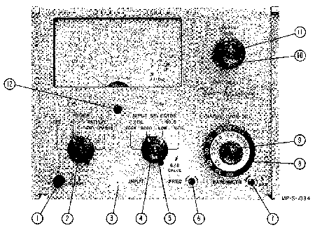
Image 1 of 2
If you have any other photos or manuals for the
Hewlett Packard 415C
you can
upload the files here.
Equipment:
415C
Date:
1962
Category:
Group:
Sub Group:
Information
1-2. The Model 415C Standing Wave Ratio Meter is a
transistorized instrument designed for measuring standing
wave ratios and attenuation. The instrument is essentially a
high-gain amplifier, tuned to an audio frequency, with a
calibrated meter output. Specifications for this instrument
are given in table 1-1. The Model 415C is calibrated to
accept inputs from square-law detectors, but because of the
high sensitivity and tuned amplifier it is also, useful as a
null detector for audio frequency bridges.
1-3. Normally the signal input to the Model 415C is taken
from either crystal (200-ohm or 200K-ohm) or bolometer (4.3
ma or 8.7 ma) detectors. Bolometer bias is adjustable by
±10% and circuit protection prevents damage to a
barretter-type bolometer if connected or disconnected while
bias current is being supplied. SWR and attenuation are
measured with high accuracy and resolution by expanding
selected segments of the normal scales to a full scale
presentation. SWR may also be measured accurately in terms
of db and then converted to a swr.
1-4. This instrument is capable of portable operation when
equipped with a battery. A battery for this use is available
initially as Option 1 and later as a$ stock item. The Model
415C has a variable tuned amplifier and an adjustable
bandwidth (15 cps to 100 cps) to meet a variety of
measurement conditions. An ac Amplifier Output is provided
on the rear panel for using the Model 415C as a high-gain
(140 db) tuned amplifier. A Recorder jack on the rear panel
permits operation with a dc recorder.
1 Manual
Service manual
Manual type:
Service manual
Pages:
66
Size:
13.2 MB
Language:
english
Revision:
Manual-ID:
01267-2
Date:
Quality:
Scanned document, all readable.
Upload date:
Aug. 7, 2015
MD5:
045667fc-6254-505e-92b3-77b4477323a1
Uploader:
Gianni Guidotti
Downloads:
523