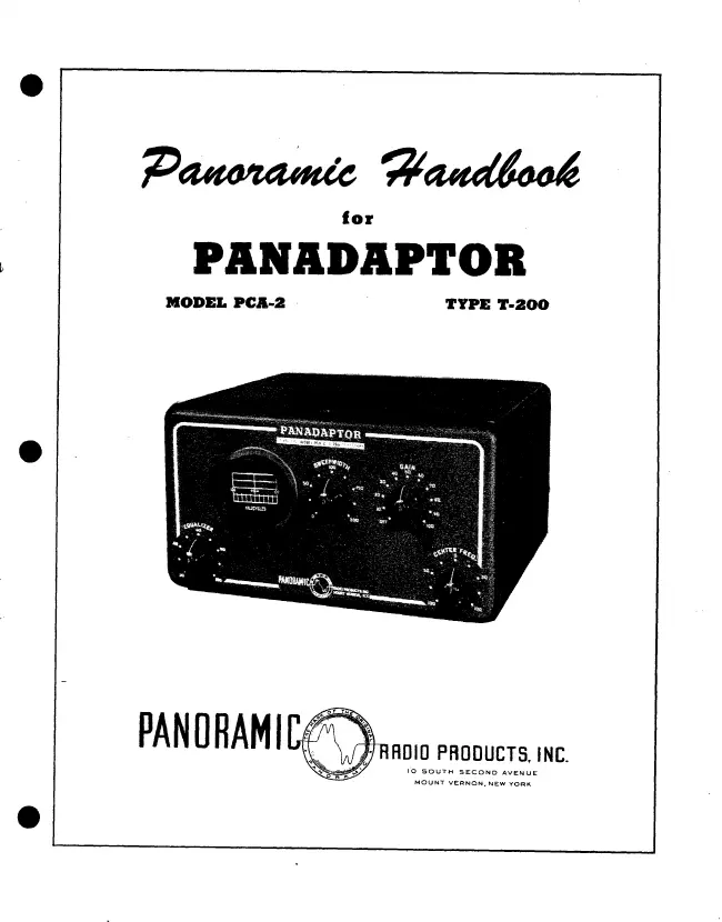
Panoramic Radio Products - PANADAPTOR MODEL PCA-2 TYPE T-200 - Receiver
Manufacturer:
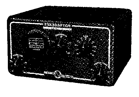
Image 1 of 1
If you have any other photos or manuals for the
Panoramic Radio Products PANADAPTOR MODEL PCA-2 TYPE T-200
you can
upload the files here.
Equipment:
PANADAPTOR MODEL PCA-2 TYPE T-200
Date:
Category:
Group:
Sub Group:
Information
1. INTRODUCTION.
The PANADAPTOR is a highly versatile piece of equipment. Its
usefulness grows continuously as ones experience with it
increases. It will make any good receiver better. But what
the PANADAPTOR does and how it does it, is of course,
determined by the receiver and the operator. The PANADAPTOR
needs intelligent handling and careful interpretation of
results.
The purpose of this handbook is to familiarize the operator
with the operation, application and interpretation of
Panoramic Reception, with PANADAPTOR Model PCA-2, Type T-200.
Please read the handbook carefully.
Complete Installation and Maintenance data for PANADAPTOR
Model PCA-2, Type T-200, are provided in individual sections.
2. GENERAL
Through its many applications, the PANADAPTOR provides
information and operating technique not obtainable in any
other way. Upon connecting the PANADAPTOR to any standard
communications receiver, both visible and audible reception
of all signals receivable within the tuning range of the
receiver are possible. The aural receiver used with Model
PCA-2 must be a superheterodyne having an I.F. between 450KC
and 470KC. It is preferable that this receiver have at least
one R.F. stage for adequate image rejection.
Note
The PANADAPTOR is factory adjusted for a mean input
frequency of 455 KC. For best results the mean input
frequency of the PANADAPTOR should match the receiver I.F.
If they do not match, the R.F. Bandpass Amplifier of the
PANADAPTOR must be realigned according to Alignment
Procedure Section V.
Six types of operation are available as follows:
a. VISIBLE PANORAMIC. Signals (within a band extending up to
100KC above and below the frequency to which the companion
receiver is tuned) appear as individual vertical “pips”, in
order of frequency, at a definite location along the
calibrated horizontal axis of the Panoramic screen.
As the receiver is tuned, the “pips” move across the screen
and “walk-off” at one side while new pips enter on the
opposite side. For any setting of the receiver tuning dial,
the “pip” appearing at the center or zero mark of the screen
represents the signal to which the receiver is tuned.
1 Manual
Service and user manual
Manual type:
Service and user manual
Pages:
39
Size:
2.3 MB
Language:
english
Revision:
Manual-ID:
Date:
Quality:
Scanned document, reading partly badly, partly not readable.
Upload date:
May 25, 2016
MD5:
f1468b8e-da80-bdf6-2812-41c77d2c560e
Downloads:
559