Pioneer - TX-8500II - Tuner
Manufacturer:
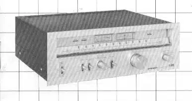
Image 1 of 1
If you have any other photos or manuals for the
Pioneer TX-8500II
you can
upload the files here.
Equipment:
TX-8500II
Date:
1976
Category:
Group:
Sub Group:
Information
Full Performance FM Front End The 1st stage RF amplifier front end includes a 4-gang variable capacitor and high gain low noise dual gate MOS FET circuit. In addition to advanced spurious, image and other types of interfering signal rejection capability, high sensitivity and excellent strong signal input response are obtained. A wide air spaced variable capacitor is also employed in the local oscillator circuit for increasing tuning scale accuracy.
Selectable Bandwidth IF Amplifier
According to signal conditions, the II amplifier can be selected for wide band (high fidelity) and narrow band (high selectivity) modes. A 2 element phase linear ceramic filter is used in the wide band mode, improving phase response to allow FM reception with excellent linearity and fidelity. The narrow band mode utilizes 4 dual element ceramic filters to obtain an effective selectivity of 80dB. Interference-free reception becomes possible even in locations where a strong interfering signal is adjacent to a desired station.
Automatic Pilot Signal Cancelling Circuit Earlier multiplex circuit designs employed 19kHz pilot signal blocking filters and thus exhibited a hint of reduction in frequency response at the high end of the band. This drawback is overcome by a newly developed PLL 1C which includes an automatic pilot signal cancelling circuit. Since carrier leakage can also be amply suppressed, the new device actually extends frequency response at high frequencies. The demodulator includes a negative feedback (NFB) circuit for improved SN ratio and minimum distortion.
Built-in Rcc Level Check Oscillator Proper tape deck recording level settings and correct antenna direction are important factors in producing quality recordings of FM broadcasts. The built-in reference signal oscillator provides a 440Hz toneburst signal at a level corresponding to 50% FM modulation for use as a recording level check signal. In addition to use when recording of FM programs, this feature is also valuable for balancing the stereo channels of the listening room equipment.
AM Tuner Includes Newly Developed 1C Tuned type AM RF amplifier circuit incorporates a newly developed high sensitivity, low distortion 1C and 2*gang variable capacitor. These contribute to advanced imaging and RF interference rejection capabilities. Since optimum AGC voltage is supplied to each section, stable reception can be obtained with low spurious interference and distortion even in high field strength areas.
AF 1C Includes Built-in Muting Circuit
Full NFB is applied in the wide dynamic range differential direct coupled audio frequency amplifier circuit, while the muting circuit incorporates the most recent electronic circuit technology. By including both these circuits in a newly developed 1C, low distortion and high S/N are realized which approach the values associated with test instrumentation. Smooth, noise-free reception is thus assured.
2 Manuals
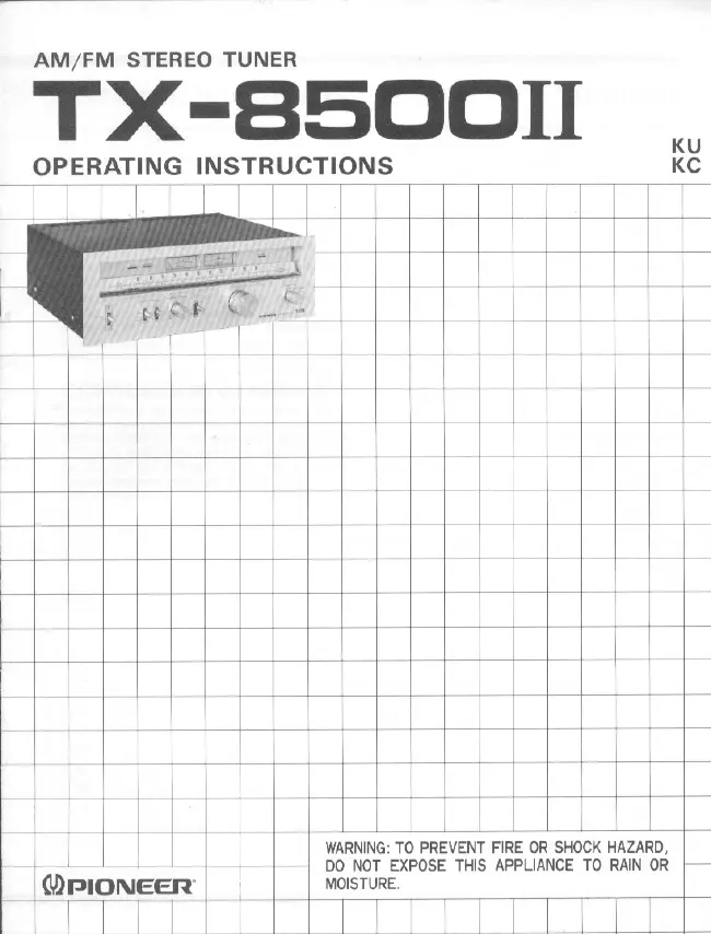
User manual
Manual type:
User manual
Pages:
12
Size:
2.2 MB
Language:
english
Revision:
Manual-ID:
Date:
January 1976
Quality:
Scanned document, all readable.
Upload date:
Aug. 30, 2020
MD5:
840947c1-f524-a3a7-cafc-fbbdac0f6d62
Downloads:
80
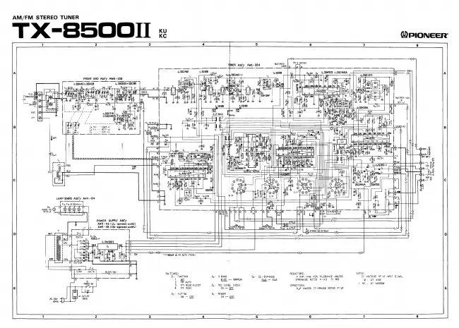
Schematics diagram
Manual type:
Schematics diagram
Pages:
1
Size:
792.8 KB
Language:
english
Revision:
Manual-ID:
Date:
Quality:
Scanned document, all readable.
Upload date:
Aug. 30, 2020
MD5:
c320f6b6-675a-184d-b33b-2c2951510624
Downloads:
77