Spilsbury Communications Ltd. - AC-31 - Antenna
Manufacturer:
No picture available!
Maybe you can
upload a pic
for the
Spilsbury Communications Ltd. AC-31 ?
If you have any other manuals for the
Spilsbury Communications Ltd. AC-31
you can
upload the files here.
.
Equipment:
AC-31
Date:
Category:
Group:
Sub Group:
Information
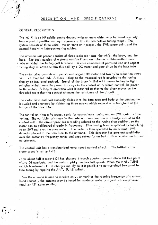
The
AC-31 is an HF mobile centre-loaded whip antenna which
may be tuned remotely from a control position on any
frequency within its two octave tuning range. The system
consists of three units: the antenna unit proper, the SWR
sensor unit, and the control head with interconnecting cables.
The antenna unit proper consists of three main sections: the
whip, the body, and the base. The body consists of a strong
outside fiberglass tube and a thin-walled inner tube on
which the tuning coil is wound. A core composed of powered
iron and copper tuning slugs is moved within this coil by a
DC motor and gear drive in the base tube.
The m* tor drive consists of a permanent magnet DC motor and
two nylon reduction gears iurni > a threaded rod. A block
riding on the threaded rod is coupled to the tuning slug by
an insulated pushrod. Travel of the block is limited to
seven inches by light switches which break the power to
relays in the control unit, which control the power to the
motor. A loop of nichrome wire is mounted so that as the
block moves on the threaded rod a shorting contact changes
the resistance of the circuit.
The motor drive and coil assembly slides into the base tube
and body ot the antenna and is scaled and anchored by
tightening three screws which expand a rubber gland at the
bottom of the base tube. : “
The control unit has a frequency scale for approximate
tuning and an SWR scale for fine tuning. The variable
resistance in the antenna forms one arm of a bridge circuit
in the control unit. The circuit provides a reading related
to the tuning slug position, so the meter can be calibrated
directly in frequency. Fine tuning is accomplished by
switching to an SWR scale on the same meter. The meter is
then operated by an external SWR detector placed in the coax
line to the antenna. This detector has constant sensitivity
over the antenna's frequency range and once set-up for an
installation requires no further adjustments.
Tie control unit has a transistorized motor speed control
circuit. The initial or low rector speed is set by R-13.
a rter about half a second Cl has charged through constant
current diode D3 to a point w'.are D2 conducts, and the
motor rapidly reaches full speed. When the ANT. TUNE switch
is released, Cl discharges rapidly so it is possible to get
sustained low speed for fine tuning by tapping the ANT. TUNE
switch.
Sen the antenna is used to receive only, or monitor the
receive frequency of a cross-bond channel, the antenna may
be tuned for maximum noise or signal or for mqximum recwi.
er "S" meter reading.
Service and user manual
Manual type:
Service and user manual
Pages:
24
Size:
476.5 KB
Language:
english
Revision:
Manual-ID:
Date:
Quality:
Scanned document, reading partly badly, partly not readable.
Upload date:
Sept. 17, 2016
MD5:
e37c70d2-0c4f-b59d-a18f-5876d076a72a
Downloads:
397
