Tektronix - 7D13 - Digital multimeter
Manufacturer:
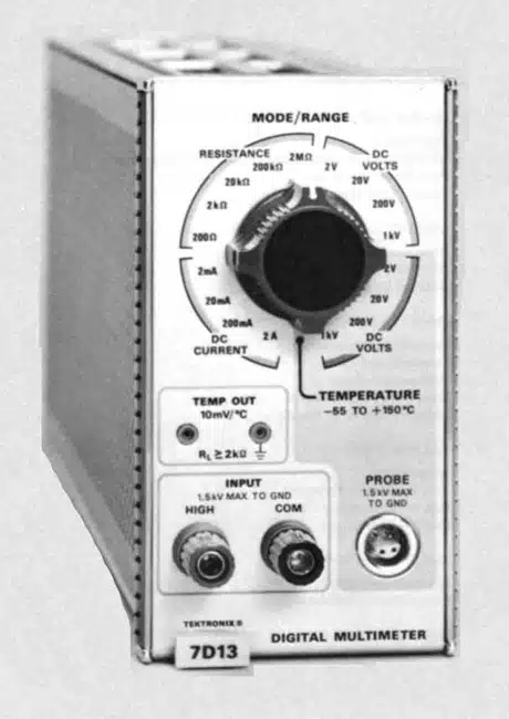
Image 1 of 1
If you have any other photos or manuals for the
Tektronix 7D13
you can
upload the files here.
Equipment:
7D13
Date:
1971
Category:
Group:
Sub Group:
Information
Introduction
The 7D13 Digital Multimeter plug in unit is designed for use
with Tektronix 7000-series Oscilloscopes equipped with a
readout system. The 7D13 can be used to measure DC voltage.
DC current, resistance, and temperature.
Temperature measurements are made with the P6058 probe or a
temperature-sensing device connected to the front-panel
PROBE connector. An analog temperature signal output is
available at the front-panel TEMP OUT
connectors regardless of the setting of the MODE/RANGE control.
The output of the 7D13 is presented as a digital readout on
the CRT of the associated oscilloscope, along with
information encoded by the other plug-in units. This display
is written by the CRT beam on a time-shared basis with the
analog waveform display from the other plug-in units.
1 Manual
Service and user manual
Manual type:
Service and user manual
Pages:
83
Size:
18.8 MB
Language:
english
Revision:
Manual-ID:
Date:
January 1971
Quality:
Scanned document, all readable.
Upload date:
April 23, 2017
MD5:
8894960a-8879-62a8-c9e5-149a2a9d5b9f
Downloads:
568