Tektronix - TR502 - Generator
Manufacturer:

Image 1 of 1
If you have any other photos or manuals for the
Tektronix TR502
you can
upload the files here.
Equipment:
TR502
Date:
1975
Category:
Group:
Sub Group:
Information
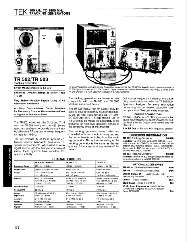
The TR 502 Tracking Generator operates with the 7L13 or 7L12
Spectrum Analyzer to provide a calibrated rf signal for
swept frequency applications from 100 kHz to 1.8 GHz. The
output frequency of the TR 502 can be adjusted to track the
spectrum analyzer frequency within 10 Hz. The TR 502, a
two-wide unit compatible with the TM 500 Modular Series
instruments, is normally used with the TM 503 (Option 07)
Power Module. This permits the optional use of a digital
counter such as the DC 508A with Option 07. A bright dot, on
the spectrum display, identifies the frequency location on
the sweep that is indicated by the counter. Higher range
counters to 1.8 GHz can be used by connecting their input to
the TR 502 AUX RF OUT connector.
The TR 502 Tracking Generator is a two wide plug-in unit for
the TM 500-Series (Option 7) Power Modules. It operates with
the 7L13 or 7L12 Spectrum Analyzer to provide a constant,
level-calibrated rf signal source, that precisely tracks the
spectrum analyzer input frequency from 100 kHz to 1.8 GHz.
Signal output level is calibrated and adjustable from 0 dBm
to -59 dBm in 1 dB steps. The Spectrum Analyzer/Tracking
Generator system can be used to display frequency response
of various devices such as filters, amplifiers, etc. that
are connected between the tracking generator RF OUTput and
the spectrum analyzer rf input connector.
When the TR 502 is installed in a modified three-wide or
larger, power module, a frequency counter such as the DC 502
can be connected to the AUX OUT and used to accurately
measure the frequency for any fixed position of span. When
the analyzer is in the non-sweep mode, the TR 502 output is
a cw signal and the counter reads continuously. If a DC 502
Option 7, or similar counter is used, the TRACKING GEN LOGIC
is interfaced with the 7L13 Spectrum Analyzer so operational
logic from the TR 502 controls the sweep function of the
spectrum analyzer and the frequency counting of the counter
A dot is displayed at sweep center to indicate where and
when the frequency count is taken.
2 Manuals
Datasheet
Manual type:
Datasheet
Pages:
1
Size:
135.7 KB
Language:
english
Revision:
Manual-ID:
Date:
Quality:
Scanned document, all readable.
Upload date:
Nov. 24, 2014
MD5:
8694e5d4-e67d-8fde-eaa0-73139cd6c6c5
Downloads:
0
Service and user manual
Manual type:
Service and user manual

Pages:
58
Size:
21.7 MB
Language:
english
Revision:
revised
Manual-ID:
070-1735-00
Date:
Quality:
Scanned document, all readable.
Upload date:
Nov. 29, 2014
MD5:
12266d84-bcc7-3e15-4536-a184f43097b6
Downloads:
0