Kikusui Electronics Corporation - TOS5101 - Test Set
Manufacturer:
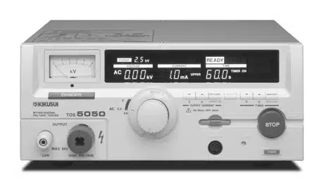
Image 1 of 2
If you have any other photos or manuals for the
Kikusui Electronics Corporation TOS5101
you can
upload the files here.
Equipment:
TOS5101
Date:
2004
Category:
Group:
Sub Group:
Information
The features common to Models TOS5101, TOS5051, and TOS5050
Testers can be summarized as follows:
1. For tests complying with major industrial standards
Each of the Tester allows you to conduct withstanding
voltage tests (dielectric strength tests) of electrical and
electronic devices and components, complying with major
industrial standards including UL, CSA, BS, and JIS
(Japanese Industrial Standards) and Electrical Equipment
Control Ordinances of Japan.
2. A Transformer's capacity is 500VA
The Tester has a transformer, rated 500VA.
3. Rational layouts of keys and switches
The keys have a slant-plane for easy viewing and convenient
operation. The switch for AC/ DC select and test voltage
range select and the control for test voltage adjustment are
installed concentrically, allowing you to operate them
conveniently with two concentric knobs. For adjustment of
pass/fail-judgement limit current setting and that of timer
setting, respective increment/decrement keys are provided.
These keys and switches, together with the large display
easy to view, are laid out rationally and will assist you to
conduct your tests accurately and efficiently.
4. A large color display
The Tester has a large color VACUUM FLUORESCENT DISPLAY. It
is a wide viewing angle type of display with high intensity,
and clearly indicates information in clearly readable large
letters and in color annunciators. The indicated information
includes test conditions, instrument status, readback
current, result of pass/fail judgement, etc., assisting you
to conduct your tests accurately and efficiently.
5. An analog voltmeter and a digital voltmeter
The Tester has both analog voltmeter (±5% FS) and digital
voltmeter (±1.5% FS) — the former for quick grasp of the
voltage and the latter for more accurate readout — assisting
you to conduct your tests rapidly but accurately.
6. A digital ammeter
The tester has a digital ammeter to measure the current that
flows through the DUT (device under test).
7. A window comparator for pass/fail judgement
The Tester has a window comparator for pass/fail judgement
with reference to both upper (U) and lower (L) criteria
(cutoff current). The comparator generates a FAIL signal
when the measured current that flows through the DUT is
greater than the preset upper limit criterion or even when
it is less than the preset lower limit criterion. The L FAIL
detection function contributes to improve the test
reliability by detecting open-circuiting or imperfect
contacting of the test leadwires. Separately for each of U
type and L type of fail, the Tester indicates a fail
annunciator message on its display and delivers a fail event
signal, allowing you to immediately find out the type of the
fail.
8. A digital timer
The timer allows you to preset the period during which the
test voltage is to be applied to the DUT. The preset range
is 0.5 to 999 seconds (in 1895 steps). When the timer
function is ON, the preset period is decremented and the
timer indicates the remaining period; when it is OFF, time
is incremented and the timer indicates the elapsed period.
9. Remote control provision
The tester has provisions for remote start/stop control
operation. That is, it has a 5-pin DIN connector (for the
optional Remote Control Box or High Voltage Test Probe) on
its front panel and a 14-pin Amphenol connector on its rear
panel. The remote control function, together with the status
signal function, will help you conduct efficient automatic
labor-saving tests.
10. Status signals
The Tester delivers seven status signals — namely, H.V ON,
TEST, PASS, U FAIL, L FAIL, READY, and PROTECTION — through
its 14-pin Amphenol connector (that is used in common for
the remote control signal also) on the rear panel. The
signal form is open collector. The Tester can deliver a 100V
AC output in response to one of eight states — namely, H.V
ON, TEST, PASS, U FAIL, L FAIL, READY, PROTECTION, and POWER
ON. As used in conjunction with the remote control function,
these status signals will help you to conduct still more
efficient automatic labor-saving tests.
12. Resume of test state by nonvolatile memory
When you turn the Tester power OFF, the Tester stores its
existing test state in its nonvolatile memory. As you turn
the Tester power ON for the next time, by recalling the
conditions of test from the nonvolatile memory the Tester
automatically restores the test state that existed when you
turned OFF power last time.
13. A safer H.V output terminal
The leadwire insertion portion of the high voltage output
terminal is structured with a restriction for safer connection.
14. A DANGER lamp
The Tester has a large and bright DANGER lamp. This lamp
lights up so far as electric charge remains on the output
terminal, warning you of a possible electric shock hazard.
15. Interlock provision
The Tester has an interlock provision to ensure that the
Tester cannot deliver its output voltage and the Tester
shutdown its output voltage under test condition unless a
certain external condition is met. This interlock signal is
available if there is open-circuiting or imperfect
contacting in the signal line, thereby enhancing further the
operation safety.
16. Keylock function
The Tester has a keylock function to disable all keys
(except the START/STOP keys) to guard against inadvertent
key operation by the operator or by key operation by
unauthorized persons, thereby improving the reliability of
tests.
17. Switches for safer operation
A rotary switch is used for AC/DC test mode selection and
test voltage range selection. The START switche is of a
recessed type. These features, together with the keylock
function, enhance operation reliability and safety.
18. Noise-resistant circuits
The internal circuits of the Tester are designed to be
highly resistant against noise, thereby enhancing the
operation reliability.
■ The features common to Models TOS5101 and TOS5051 (models
for DC output also) can be summarized as follows:
1. Automatic discharge function
When the DC test output voltage is turned off, the output
circuit is automatically discharged, thereby discharging the
charge that could remain in the device under test (DUT).
This feature, together with the DANGER lamp, enhances the
test operation safety.
2. A DC/DC converter for quality DC test voltage
The Tester has a DC/DC converter which generates a quality
test voltage of high stability with less ripple.
1 Manual
User manual
Manual type:
User manual
Pages:
139
Size:
15.3 MB
Language:
english
Revision:
Manual-ID:
Z1-000-632 IB000598
Date:
March 2004
Quality:
Scanned document, all readable.
Upload date:
Sept. 2, 2017
MD5:
fe0ad489-64ca-cfbd-4500-9fea711214eb
Downloads:
1467