Fluke - 2205A - Control Unit
Manufacturer:
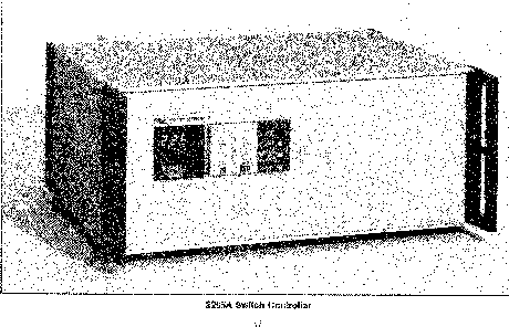
Image 1 of 1
If you have any other photos or manuals for the
Fluke 2205A
you can
upload the files here.
Equipment:
2205A
Date:
1982
Category:
Group:
Sub Group:
Information
1-1. INTRODUCTION
1-2, The Fluke Model 2205A Switch Controller is an
instrument mainframe which accepts plug-in options for
multi-function switching of analog signals. The 2205A is
designed for automatic test equipment (ATE) and data
acquisition system use. The switch modules functionally
accomodate the three fundamental requirements for switching
in instrumentation systems: signal aquisition, distribution,
and control.
1-3. The key feature of the 2205A is its modular
configuration which supports concurrent multi-function
switching. Other important features include: low thermal
design for low level measurment applications, dual guarded
internal scanner bus for precision resistance measurements
or parallel scanning, and expansion capability. In its basic
form, the 2205A is capable of physically housing up to 10
switch modules and can be expanded to electrically control
up to 100 switch modules. The 2205A is also compatible with
companion instruments for system application.
1-4. The front panel of the 2205 A features the controls and
indicators necessary for manual (local) control of the
switch modules. Commands are entered on a calculator- type
keyboard (0-9) and are displayed on a three-digit LED
display. Three control buttons (BLOCK RESET/T.C. REF.
JUNCTION, LOCAL, and INCREMENT) are provided for commanding
thermocouple reference junction measurements or module
resets (depending on type of module addressed), local recall
(remote-to-local), and channel increment.
1-5. The rear panel of the 2205A includes a remote interface
connector (for use on IEEE-488 or RS-232-C Standard buses),
an extender connector to add extention mainframes, an analog
connector for connecting the internal scanner buses to an
external instrument such as a digital multimeter (DMM), and
a trigger output connector for initiating a DMM reading. An
analog output cable for connection between the 2205A and a
system type DMM is supplied with the 2205A. The remote
interface cable, the trigger output cable (coax with BNC
connectors), and an extender cable (which is required when
adding a extension chassis) are options and are not included
with the unit. Extender cables are available as accessories
and are fabricated by the factory to meet particular cable
length requirements. Cable lengths from 3 to 1500 feet may
be used depending upon the extention mainframe employed.
1 -6. The slots for the switch modules are also located at
the rear of the 2205A. They consist of a series of 10 pcb
slots (blocks) numbered from 0 through 9. Each slot will
accommodate a plug-in relay pcb and an input connector for
supplying analog data to the 2205A. The relay pcbs and the
input connectors make-up a module are available as options.
1-7. All options and accessories available for use with the
2205A are listed in Table 1-1. Details necessary for
specification, installation, operation, and maintenance are
given in Section 7 of this manual.
1 Manual
Service and user manual
Manual type:
Service and user manual
Pages:
154
Size:
7.3 MB
Language:
english
Revision:
Manual-ID:
633644
Date:
Quality:
Scanned document, all readable.
Upload date:
Feb. 8, 2016
MD5:
b2f8e2b7-74c0-1f09-37c6-efc3aae0f439
Downloads:
493