Fluke - 8505A - Digital multimeter
Manufacturer:
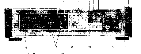
Image 1 of 3
If you have any other photos or manuals for the
Fluke 8505A
you can
upload the files here.
Equipment:
8505A
Date:
1990
Category:
Group:
Sub Group:
Information
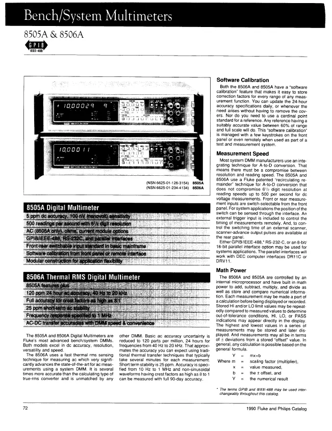
The 8505A and 8506A Digital Multimeters are Fluke's most
advanced bench/system DMMs. Both models excel in dc
accuracy, resolution, versatility and speed.
The 8506A uses a fast thermal rms sensing technique for
measuring ac which very significantly advances the
state-of-the-art for ac measurements using a system DMM. It
is several times more accurate than the calculating type of
true-rms converter and is unmatched by any
other DMM. Basic ac accuracy uncertainty is reduced to 120
parts per million, 24 hours for frequencies from 40 Hz to 20
kHz. That approximates the accuracy you can expect using
traditional thermal transfer techniques that typically take
several minutes for each measurement. Short term stability
is 25 ppm. Accuracy is specified from 10 Hz to 1 MHz and
non-sinusoidal waveforms having crest factors as high as 8
to 1 can be measured with full 90-day accuracy.
Software Calibration
Both the 8506A and 8505A have a “software calibration”
feature that makes it easy to store correction factors for
every range of any measurement function. You can update the
24-hour accuracy specifications daily, or whenever the need
arises without having to remove the covers. Nor do you need
to use a cardinal point standard for a reference. Any
reference having a suitably accurate value between 60% of
range and full scale will do. This "software calibration” is
managed with a few keystrokes on the front panel or even
remotely when used as part of a test and measurement system.
Measurement Speed
Most system DMM manufacturers use an integrating technique
for A-to-D conversion. That means there must be a compromise
between resolution and reading speed. The 8505A and 8506A
use a Fluke patented “recirculating remainder” technique for
A-to-D conversion that does not compromise 6Ίζ digit
resolution at reading speeds up to 500 per second for dc
voltage measurements. Front or rear measurement inputs are
switch-selectable from the front panel. For system
applications the position of the switch can be sensed
through the interface. An external trigger input is included
to control the timing of measurements remotely. And, to
control the switching time of an external scanner,
scanner-advance output pulses are available at the rear panel.
Either GPIB/IEEE-488,* RS-232-C, or an 8-bit/ 16-bit
parallel interface option may be used for systems
applications. The parallel interfaces will work with DEC
computer interfaces DR11C or DRV11.
2 Manuals
User manual with schematics
Manual type:
User manual with schematics

Pages:
323
Size:
18.3 MB
Language:
english
Revision:
Rev. 3
Manual-ID:
638841
Date:
Quality:
Scanned document, all readable.
Upload date:
Oct. 1, 2008
MD5:
32135cb5-0b2a-7934-b9dd-7f17fb0fab04
Downloads:
6965
Datasheet
Manual type:
Datasheet
Pages:
5
Size:
671.1 KB
Language:
english
Revision:
Manual-ID:
Date:
Quality:
Scanned document, reading partly badly, partly not readable.
Upload date:
Jan. 28, 2016
MD5:
07971e36-fd58-b6b7-fc0e-591282ea318b
Downloads:
1203