Gates Radio Company - M-5790 BC-1T - Transmitter
Manufacturer:
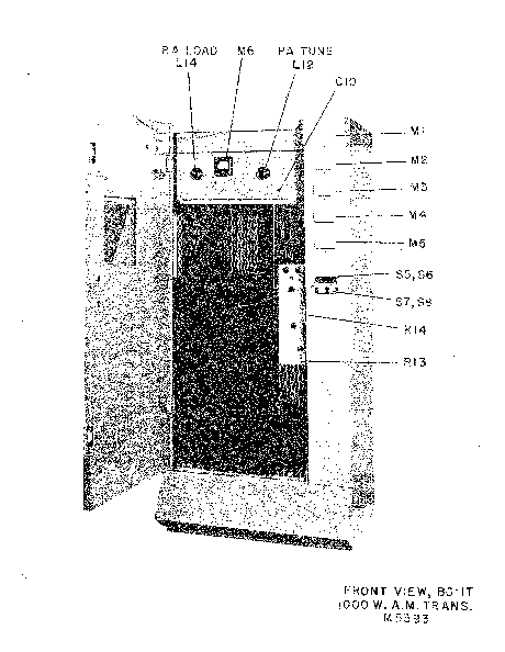
Image 1 of 3
If you have any other photos or manuals for the
Gates Radio Company M-5790 BC-1T
you can
upload the files here.
Equipment:
M-5790 BC-1T
Date:
1961
Category:
Group:
Sub Group:
Information
THE FOLLOWING SPECIFICATIONS ARE TYPICAL AND MAY VARY
SLIGHTLY WITH VARIOUS MODES OF OPERATION:
1. Rated power output: 1000/250 watts. Capable of 1100/275
watts where directional systems induce losses.
2. Frequency range: 1600 Kc to 5^0 Kc at the frequency you
ordered.
3. Power input: 230 volts, 3 wire, solid neutral, single
phase, either 50 or 60 cycles. Provide #4 or larger primary
wiring from entrance box to transmitter. Transmitter will
consume approximately 4000 watts at 100% modulation.
4. Frequency stability: + 10 cycles.
5* Audio input: + 12 db + 2 db for 100% modulation for both
output powers. The output of a Gates SA-39B limiter should
be correct for this. If other limiter or audio amplifier is
used, be sure and check output capabilities.
6. Input audio impedance: As supplied, 600 ohms, which will
also match 500 ohm impedance. It may be connected for
150/250 ohms if desired.
7- Distortion: Rated at 3% from 50 to 10,000 cycles but
capable of much better at many frequencies.
8. Noise: 60 db or better below 100% modulation.
9» Carrier shift: 3% or less between 0 and full
modulation-provided wire size in Point 3 (above) is followed
and R.F. load is correctly tuned.
10« R.F. output impedance: Will match loads from 50 to 70 ohms.
An antenna coupling unit is usually necessary to match the
antenna tower.
OTHER HELPFUL DATA:
(a) Provision for 2 vacuum type crystals and holders. If you
wish a spare, order M5602, giving your frequency.
(b) The inbuilt dummy antenna will accept 100% modulation
and is for 51*5 ohms. See Par. 4 under "How Can We Help
You?" in the-back of this manual, entitled "Computing Power
Output".
The dummy antenna is substituted for the tower.
(c) THE TWO TOP SUCTION FANS can do their best in cooling
performance by periodical replacement of the removable air
filters located at the front bottom of the transmitter.
Order Type M5825 and two are required. The time cycle in
replacing filters depends on dust conditions. Normally about
three times annually.
1 Manual
Service and user manual
Manual type:
Service and user manual
Pages:
73
Size:
5.1 MB
Language:
english
Revision:
Manual-ID:
Date:
February 1961
Quality:
Scanned document, reading partly badly, partly not readable.
Upload date:
May 14, 2015
MD5:
ae5b5bcb-dd8e-e8b6-e120-da54ee08b9b6
Downloads:
584