Drake - SP75 - Sonstiges
Hersteller:
Gerät:
SP75
Datum:
Kategorie:
Gruppe:
Untergruppe:
Informationen
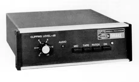
The SP75 Speech Processor is designed to provide an increase
in average power and readability of a single sideband voice
signal during weak signal or high interference conditions.
The SP75 is connected between the microphone and microphone
input of the single sideband transmitter, thus requiring no
modification of the existing transmitter or transceiver. A
front panel switch allows the processor to be switched in or
bypassed as conditions warrant. Two additional inputs, such
as a tape player or phone patch, may be front panel selected
in place of the normal microphone input.
The amount of RF envelope clipping is adjustable between
zero and twenty decibels by a front panel control. A LED
indicates proper audio input level. Because of the
pre-clipping audio compression, small changes in voice
levels do not widely affect the clipping level.
Muting circuitry reduces gain during speech pauses, thus
reducing undesirable background noise pickup and allowing
VOX operation with the processor on.
The SP75 was designed for optimum performance using the
Drake model 7077 microphone and the Drake TR7 transceiver or
Drake 4-line transmitters. However, excellent performance
can be obtained with most other transmitters which have a
microphone input impedance of approximately 50 K ohm or
greater. Microphones other than the Drake 7077 may be used
successfully. However, microphones with a more sharply
rising frequency response may produce a less pleasant
response than a microphone with a flatter response.
1 Handbuch
Reparatur und Bedienungsanleitung
Dokumenttyp:
Reparatur und Bedienungsanleitung
Seitenanzahl:
15
Größe:
1,3 MB
Sprache:
Englisch
Revision:
Dokument-ID:
Datum:
Qualität:
Gescanntes Dokument, alles ist lesbar.
Upload Datum:
9. August 2017
MD5:
15a447f2-e412-3038-8d7b-81f2f9a37004
Downloads:
499