
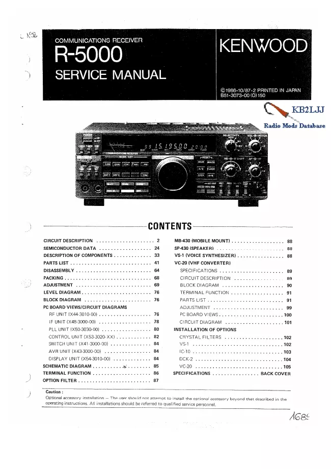
Kenwood - R-5000 - Receiver
Hersteller:
Kein Bild verfügbar!
Vielleicht können sie für ein
Kenwood R-5000 ?
Ein
Foto hochladen
?
Weitere Anleitungen und Fotos für ein
Kenwood R-5000
können sie
hier hochladen.
Gerät:
R-5000
Datum:
1986
Kategorie:
Gruppe:
Untergruppe:
Informationen
The R-5000 is a double-conversion general-coverage receiver
with a first IF (intermediate frequency) of 58.1125 MHz and
second IF of 8.83MHz. (In the FM mode triple conversion is
used with a third IF of 455kHz.) It can receive AM, LSB,
USB, CW, FM, and RTTY signals from 30kHz to 30MHz, with
performance specifications guaranteed from 100kHz up. The
VC-20 VHF converter option extends the receiving range to
108MHz to 174MHz.
Interference is removed by an IF filter switching circuit
and 0-to~30dB RF attenuator. The receiver also has an IF
shift feature, AF notch filter (not used in the CW mode),
and AF peak filter (CW mode only).
The receiver's phase-locked loops operate under
microprocessor control. High frequency stability and
accuracy are achieved by a single-crystal system that
provides digital frequency control in 10Hz steps. This
includes the frequencies of the VHF converter.
Other major features of the R-5000 receiver are
1. Reduction of many types of impulse noise controlled by
two noise blanker switches and a noise-blanker level control.
2. Two digital VFOs (Variable-Frequency Oscillators).
3. Direct entry of frequencies thru the use of numeric keypad.
4. A memory that stores band, mode, and antenna (1 or 2)
information for 100 channels.
5. Memory scanning and ten types of programmed scanning.
6. A built-in timer and dual-time clock.
7. Display dimmer.
8. The VS-1 voice synthesizer option internal installation.
9. Possible interfacing to a personal computer.
10. A rechargeable lithium backup battery for the
microprocessor.
11. A built-in AC power supply (the receiver can also
operate on an external DC power supply.
1 Handbuch
Reparaturanleitung
Dokumenttyp:
Reparaturanleitung
Seitenanzahl:
109
Größe:
12,6 MB
Sprache:
Englisch
Revision:
Dokument-ID:
B51-3073-00
Datum:
Januar 1986
Qualität:
Gescanntes Dokument, teilweise schwer oder teilweise nicht zu lesen.
Upload Datum:
15. April 2018
MD5:
e1f9fe32-ce47-50aa-3adf-6effbb0f965a
Downloads:
534