Philips - PM 3214 - Oszilloskop
Hersteller:
Gerät:
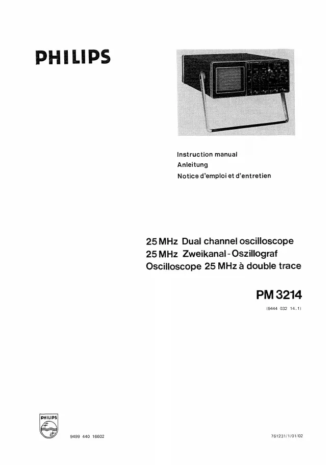
PM 3214
Datum:
1976
Kategorie:
Gruppe:
Untergruppe:
Informationen
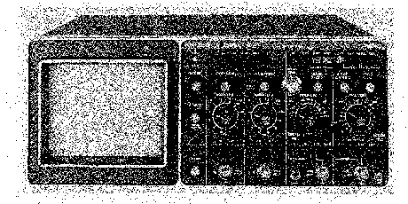
The 25 MHz dual-channel oscilloscope PM 3214 is a compact, portable instrument, ergonomically designed to facilitate its extensive measuring capabilities.
The instrument provides both a main and a delayed timebase with provision for alternate timebase displays, comprehensive triggering facilities including peak-to-peak Auto, DC coupling and automatic TV waveform display.
A large 8 x 10 cm screen with illuminated internal graticule iines makes for easier viewing, and a 10 kV accelerating potential gives a high intensity trace with a well-defined spot.
A double-insulated power supply allows the frame ground to be directly connected to floating ground circuits provided that this ground does not carry live potentials. By this means, interference by ground currents, as is frequently experienced with grounded oscilloscopes, is also substantially reduced.
The wide range of applications enabled by the above features is further extended by a versatile power supply that enables the instrument to be operated from any line voltage or frequency as well as from d.c. For field operation an optional battery version is also available.
1 Handbuch
Reparaturanleitung
Dokumenttyp:
Reparaturanleitung
Seitenanzahl:
99
Größe:
24,2 MB
Sprache:
Englisch, Deutsch, Französisch
Revision:
Dokument-ID:
9444 032 14..1 9499 440 16602
Datum:
Dezember 1976
Qualität:
Gescanntes Dokument, alles ist lesbar.
Upload Datum:
31. Juli 2020
MD5:
19a20ca4-d918-e221-ff1d-b4aed93b1737
Downloads:
419