Racal - 9081 - Generator
Hersteller:
Gerät:
9081
Datum:
1976
Kategorie:
Gruppe:
Untergruppe:
Informationen
INTRODUCTION
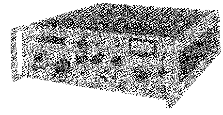
1.1 The 9081 and 9082 are synthesized signal generators
designed primarily for the testing of radio communications
equipment. Although providing the precision of a
synthesizer system locked to a high-stability frequency
standard they retain the versatility of analogue-type tuning.
RF TUNING
1.2 A major feature of the instruments is their
'single-knob' tuning allied to a channelized mode of
operation. This enables the instruments to be tuned in steps
according to the channel spacing required. The r.f. tuning
automatically locks into the centre frequency of the
particular channel. Selection of the HOLD position on the
front panel switch then electronically disconnects the spin
wheel.
1 .3 A fine tune facility provides for interpolation between
channels, and this can also be carried out by an external
slow sweep voltage if desired. The carrier frequency is
displayed on an 8-digit LED readout in which the resolution
is varied to suit the particular tuning mode (Fast, Slow or
Hold) in use.
1.4 The Channel Spacing switch provides ten different
frequency spacings which conform to the internationally
agreed requirements of different authorities. A continuous
tuning facility (Zf) is provided in which the frequency
increments are reduced to a minimum value when using SLOW
tune mode.
RF OUTPUT
1.5 Automatic levelling maintains the output typically
within ±0.5dB over the entire frequency range. A switched
attenuator and vernier control provide an output
range from -130dBm to +3dBm, (+13dBm for models 9081H and
9082H), calibrated in both dBm and voltage units. An output
switch provides a multiply-by-two facility which permits a
doubling of the normal output levels in CW, FM and Phase
Modulation modes.
MODULATION FACILITIES
1.6 AM, FM and Phase Modulation (ζ2Μ) facilities are
provided. Three spot modulation frequencies (400Hz, 1kHz and
5kHz) are available from an internal oscillator.
External modulation can also be used, the maximum
frequencies permitted being 100kHz for FM, 5kHz for $M,
100kHz for AM on Model 9081 and 20kHz for AM on Model 9082.
1.7 The meter indicates both external and internal
modulation, and, as these can be applied simultaneously,
various arrangements of multiple modulation are feasible
(see para 2.4).
POWER SUPPLY
1.8 The instruments operate from nominal 110V or 220V a.c.
supplies, 45 to 440Hz.
Mains voltage selection is by means of two rear panel
switches which provide four
possible voltage selections and can be locked to the chosen
positions by a screwed plate, which allows the selected
voltage range markings to be seen. Refer to para. 5.1.
HANDBOOK NOTES Frequency Range
1.9 Although the signal generators have a specified
operating range extending to 520MHz, the design capability
is at least 540MHz. This higher figure with its range
subdivisions is used in the technical descriptions except
when referring to the actual operating ranges.
1 Handbuch
Reparatur und Bedienungsanleitung
Dokumenttyp:
Reparatur und Bedienungsanleitung
Seitenanzahl:
153
Größe:
6,8 MB
Sprache:
Englisch
Revision:
Dokument-ID:
WOH 7204
Datum:
August 1983
Qualität:
Gescanntes Dokument, alles ist lesbar.
Upload Datum:
25. Oktober 2015
MD5:
39ddb6d7-9961-3316-b1d9-4ab896a050f5
Downloads:
924