Systron Donner - 1702 - Generator
Hersteller:
Gerät:
1702
Datum:
1982
Kategorie:
Gruppe:
Untergruppe:
Informationen
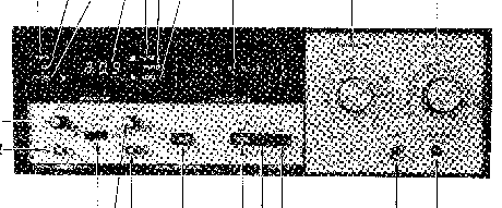
The Systron Donner Model 1702 is a frequency synthesizer
that generates fundamental (non-harmonic) signals from
100 Hz to 999.9999 MHz in discrete 100 Hz steps. Selection
of AM and FM modulation of the output is provided
either by an internal 1 kHz source or by an external
dc to 20 kHz source. The internal and external modulation
features may be used simultaneously as well as the AM
and FM inodes. The internal 1 kHz modulation source is
available as a Front Panel BNC output. This feature
provides many uses, including modulation drive for
a FM transmitter when adjusting frequency deviation.
A CW mode is also provided to allow generation of an
unmodulated carrier.
The Signal Generator's output is continuously variable
from 0.1 µV to 1 Vrms (-127 to +13 dBm) by a Front
Panel 20 dB vernier control and six step attenuator.
The Signal Generator's output is protected against
input/output overloads of over ±10 V peak, with Front
Panel reset.
Options 06 and 07 allow IEEE-488 General Purpose
Interface Bus (GPIB) control of the frequency selection,
mode selection, output level, step attenuator, selection
and status reporting for systems integration. Information
pertaining to the IEEE STD-488 GPIB as it relates
to the Model 1702 is found in various chapters of
this manual.
The Signal Generator is normally referenced to an
internal 1 MHz oscillator having a stability of
7 x 10⁻⁹ parts per day, or the high stability optional
internal reference oscillator having a 3 x 10⁻⁹ parts
per day stability. On the Rear Panel, one BNC connector
allows monitoring of the 1 MHz reference, while an
other BNC (EXT CLOCK IN) provides for inputs of external
1, 2, 5 or 10 MHz sources from a frequency standard.
1 Handbuch
Reparatur und Bedienungsanleitung
Dokumenttyp:
Reparatur und Bedienungsanleitung
Seitenanzahl:
331
Größe:
31,5 MB
Sprache:
Englisch
Revision:
Revised
Dokument-ID:
120007-01
Datum:
Qualität:
Gescanntes Dokument, alles ist lesbar.
Upload Datum:
20. Januar 2013
MD5:
ceb21af0-2a53-e720-088b-89a6ce779093
Downloads:
882