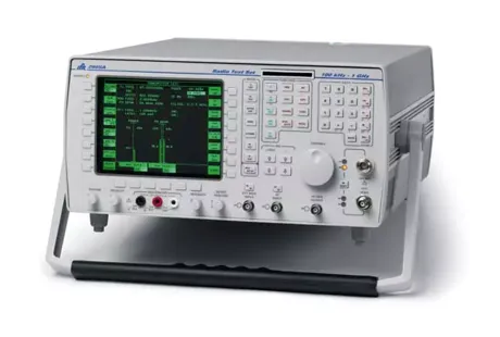
Aeroflex - 2968 - Communications Test Set
Manufacturer:

Image 1 of 1
If you have any other photos or manuals for the
Aeroflex 2968
you can
upload the files here.
Equipment:
2968
Date:
2006
Category:
Group:
Sub Group:
Information
The Radio Test Sets 2965A, 2966A, 2967 and 2968 provide comprehensive measurement systems
for all types of mobile radio testing applications. This embraces personal mobile radio (simplex
and duplex) and cellular systems. The 2967 includes digital cellular (GSM) capabilities, while the
2968 includes digital trunked system (TETRA) test facilities. These test sets are suitable for
making high performance radio system measurements in research and development, production
and maintenance.
Unless specifically stated, the information in this manual applies to all four types of test set.
A high-performance, full-span RF spectrum analyzer with tracking generator is provided. This
has features to enable component and sub-unit testing in addition to precision transmitter
measurements. A 20 Hz to 40 kHz AF spectrum analyzer is provided to ensure total measurement
capability.
The large, bright display has soft keys at each side and beneath it. With the logical layout of the
dedicated keys, this allows the many types of measurements of which the test set is capable, to be
carried out quickly and easily.
An important operating feature is the ability to use several forms of automatic control and
interfacing standards. These include IEEE 488.2 and RS 232 remote control as well as a parallel
printer port.
Features
The main facilities and features of the test set are outlined below. The operation of these and the
many minor features are explained at appropriate points in the operating instructions.
1 GHz analogue signal generator
There is a high-performance signal generator with a fast switching speed and a usable output up to
1.15 GHz. It has an oven-controlled crystal oscillator reference which has an ageing rate of less
than 2x10⁻⁷/year.
The 2965A has a maximum output of +13 dBm with ±1.5 dB accuracy.
The 2966A, 2967 and 2968 have maximum outputs of +10 dBm with ±1.75 dB accuracy.
Digital signal generator
A digital signal generator is included in the 2966A, 2967 and 2968. The following table shows
the main specification points of this for each particular instrument type. The figures shown may
be restricted when some options are included.
Comprehensive LF generators
There are three modulation sources and three audio sources within the test set. The modulation
sources can each generate signals between 20 Hz and 20 kHz; the audio sources from 1 Hz to
20 kHz. Signalling tones and data can be produced for modulation and as audio output.
The sources can be combined to produce a single source with a range of 1 Hz to 100 kHz.
Duplex operation
There is provision for simultaneous measurements on a transmitter and a receiver, with no limit to
the frequency offset between them.
Broad-band power meter
There is an accurate power meter for measurements over the range 1 mW to 150 W with an
accuracy of ±7%. The accuracy is traceable to international standards.
Selective power meter
Selective power measurements are possible with a sensitivity of −90 dBm. This allows power
measurements to be made on selected channels with multiple signals present.
50 W continuous power rating
The test set can handle up to 50 W continuous power on its N-type connector RF in/out port and
up to 150 W for short periods of time.
RF power protection
The sensitive TNC connector RF in/out port is protected from accidental overloads up to 10W.
This avoids unnecessary repair bills and wasted time.
Full span spectrum analyzer
There is a full-span spectrum analyzer to 1 GHz with centre-span and 80 dB dynamic range. The
spurious and harmonic performance of a radio can be measured with auto and user-selected
resolution bandwidth.
Tracking generator
This is operative over the full range of the spectrum analyzer. The tracking generator has a
variable output level. Measurements can be made on filters and duplexers and in RF circuit
development applications. Additionally, an offset sweep is available for mixer and IF testing, for
both up and down conversions. Doubler (×2) and divider (÷2) functions are also available.
Fast audio analyzer
There is a comprehensive analyzer for audio input and demodulated RF input signals up to 40 kHz
with a minimum span of 50 Hz and a dynamic range of 60 dB. Because it uses an FFT, harmonic
and spurious analysis can be performed very quickly. Two markers with full annotation are
provided. A stepped audio signal is available up to 20 kHz for audio circuit analysis.
500 kHz digital storage oscilloscope
There is an oscilloscope that is operative up to 500 kHz. It can be used to look at the demodulated
audio signal. The trace can be stored and the results can be read over the bus or printed out.
There are two markers with full annotation for measuring rise and fall times.
Built-in multimeter
There is provision for measuring voltage, current and resistance, and for continuity testing. The
multimeter also has the advantage that it can be controlled over the bus, so can be included in an
automatic test system.
Comprehensive range of demodulation and audio filters
A 300 Hz to 3.4 kHz band-pass and 300 Hz, 5 kHz and 20 kHz low-pass filters are provided. In
addition to these, CCITT and C-message (CMESS) psophometric filters are provided.
Rx=Tx Key
This is used to set the signal generator frequency to match the transmitter frequency automatically.
This saves time and effort when making simplex radio measurements. A duplex offset can also be
set for when the transmitter and receiver frequencies are different.
Channel key
It is possible to set up the frequency of the first channel and the channel spacing. Then, instead of
having to set a particular frequency, a channel number can be entered.
Display expanded modes
Parts of the display can be expanded to show more information. For example, in duplex testing,
the display can be expanded just to show the transmitter or receiver information. This does not
affect the operation of the test set. Expanded displays show more information and provides access
to more functions. Oscilloscope and analyzer displays can also be expanded to fill the entire
screen. This gives a larger trace for tuning and further adjustment.
Cellular and trunked radio systems
There are options for testing cellular and trunked radio systems, both analogue and digital, as
shown below.
These are fitted internally, so the size is not increased. A number of automatic test programs are
built in, and bit-level diagnostics are available for protocol analysis.
1 Manual
User manual
Manual type:
User manual
Pages:
301
Size:
2.8 MB
Language:
english
Revision:
Issue 15
Manual-ID:
46892/274
Date:
January 2008
Quality:
Electronic document, no scan, very well readable.
Upload date:
Jan. 13, 2023
MD5:
77d8fcb9-673f-2256-5d39-d385b020eebd
Downloads:
0
