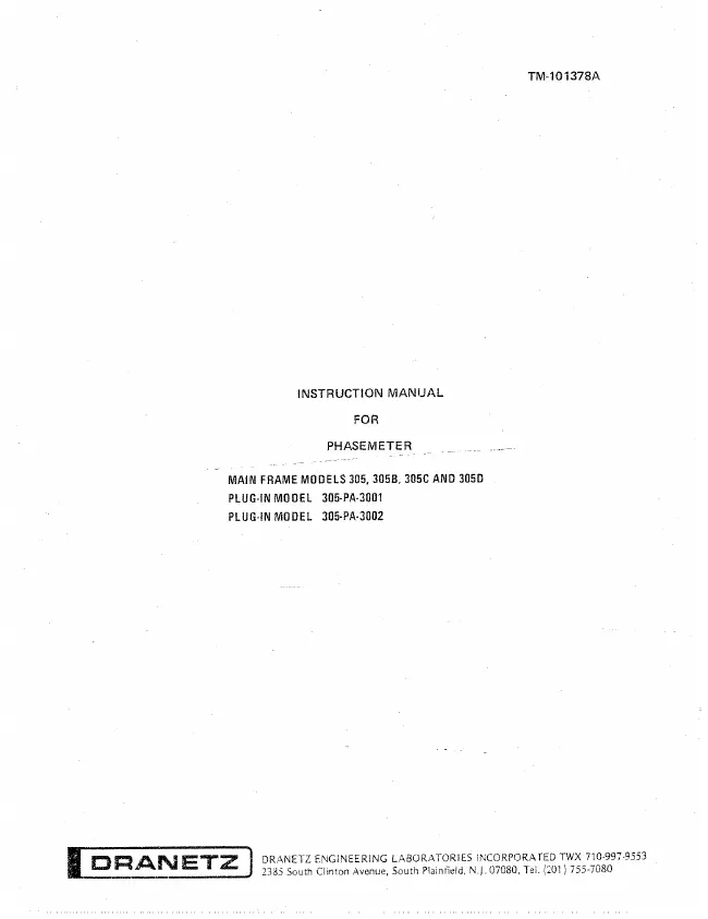
Dranetz Engineering Laboratories Inc. - 305C - Level Meter
Manufacturer:

Image 1 of 1
If you have any other photos or manuals for the
Dranetz Engineering Laboratories Inc. 305C
you can
upload the files here.
Equipment:
305C
Date:
Category:
Group:
Sub Group:
Information
Model 305 Phasemeter (figure 1-1) represents a totally
new concept in the measurement of phase angle. A precision
phase angle measurement is obtained simply by connecting the
signals and reading the display. No adjustments are required
during normal use. Model 305 senses the signal frequency and
adjusts its output time constant for maximum speed
commensurate with low ripple. It remains operational in the
presence of up to 10% high frequency noise. Model 305
sensitivity to waveform distortion is reduced over that of
other phasemeters which normally require filters to remove
distortion effects.
1-5. The use of the automatic dual mode switching allows for
continuous phase plotting between <-160° to > +340° with no
discontinuities. The front panel controls on Model 305 main
frame are used only for self checking of the main frame and
calibration of remotely connected accessories such as a
recorder or printer.
1-6 . Standard plug-in units covering a frequency range
of 1 Hz to 11 MHz are available with Model 305 Phasemeter.
Special plug-in units are available on request.
1-7. SPECIAL FEATURES
1-8. Model 305 provides special features when used with
Plug-in Model 305-PA-3001 or 305-PA-3002.
a. No operating controls.
b. Excellent stability -~ no operating adjustments.
c. 0.05° accuracy independent of input voltage.
d. Versatile plug-in concept.
e. Basic frequency range: 2 Hz to 700 kHz (extendable to I
Hz or 11 MHz with other plug-ins).
f. Digital readouts on Models 305B, 305C and 305D.
g. Digital outputs on Models 305B, 305C and 3&5D-for use
with printers, etc.
h. 1 Megohm input impedance.
i. Levels extendable to 40 KV using Tektronix probes.
j. Indicator lights on each input to indicate either low or
high input levels (305-PA-3001 only).
k. High overvoltage capability.
1 Manual
Service and user manual
Manual type:
Service and user manual
Pages:
174
Size:
6.3 MB
Language:
english
Revision:
Manual-ID:
TM-101378A
Date:
Quality:
Scanned document, reading partly badly, partly not readable.
Upload date:
Aug. 11, 2017
MD5:
dca724b8-00cf-8bea-21ca-6b720496f6ac
Downloads:
1888
