Fluke - 2180A - Thermometer
Manufacturer:
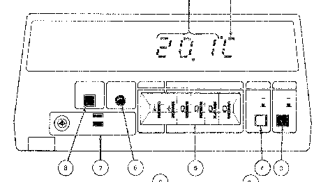
Image 1 of 1
If you have any other photos or manuals for the
Fluke 2180A
you can
upload the files here.
Equipment:
2180A
Date:
Category:
Group:
Sub Group:
Information
1-2. The Model 2180A Digital Thermometer is a portable, five
digit RTD thermometer. Temperature measurements are
possible, depending on RTD type employed, over a range
of-219°C to +664°C (-394°F to + 1435°F) with 0.1° or .01°
resolution. The instrument features:
1. Front Panel switch selection of Fahrenheit or Celsius
readings.
2. Switch selectable RTD inputs.
3. Switch selectable input line voltage.
4. Dual slope measurement techniques.
5. Digital linearization of the RTD inputs.
1-3. DESCRIPTION
I-4. The instrument display features seven, high- intensity,
seven segment LEDs, and leading zero suppression. Six of the
LEDs are used to display numeric data, with a minus sign for
negative temperature readings. The remaining LED displays
the selected temperature scale character (°F or °C).
I-5. A four connection, screw-type terminal block is
provided on the removable Input PCB for RTD connections.
Input switch settings on this module will determine the
microcomputer program necessary to linearize the desired
RTD’s input. A precision, four-wire resistance measurement
of the RTD is routed through this module to the
thermometer’s input circuitry.
1-6. Selection of the temperature scale for display is made
with a front panel pushbutton. The scale selected, Celsius
or Fahrenheit, is displayed as the last character in the
temperature reading (°C or ° F). A scale change can be made
at any time, and has no effect on calibration of the instrument.
1-7. Options and accessories available for the 2180 A are
listed in Table 1-1. More information concerning these items
is given in Section 6 of this manual, Option and Accessory
Information.
1-8. The measurement range of the 2180A Digital Thermometer
is determined by the type of RTD used as the input device.
RTD Types and total instrument accuracy specifications are
listed in Table 1-2. Linearization of the RTD input is
accomplished through toggling of the input switch segments
on the RTD Input Module. Switch positions, numbers and
applications are printed on the removable module beside the
switch.
1-9. Four input line voltages are available for switch
selection. Selection may be made for 100, 120, 220 or 240
volts ±10% as required to meet local conditions. Frequency
may vary between 50 and 440 Hertz for all voltage
selections. Refer to Section 4 of this manual when changing
the selected input line voltage.
1 Manual
Service and user manual
Manual type:
Service and user manual
Pages:
94
Size:
4.2 MB
Language:
english
Revision:
1
Manual-ID:
489211
Date:
Quality:
Scanned document, all readable.
Upload date:
Feb. 8, 2016
MD5:
d2ca2f73-e6ba-e06a-5d3f-7ba26bc7b626
Downloads:
564