Hewlett Packard - 11971 - Generator
Manufacturer:
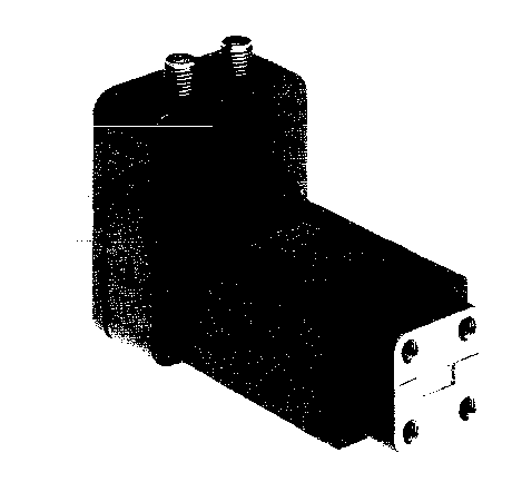
Image 1 of 1
If you have any other photos or manuals for the
Hewlett Packard 11971
you can
upload the files here.
Equipment:
11971
Date:
1985
Category:
Group:
Sub Group:
Information
The HP Models 1197IK, 11971 A, 11971Q, 1197IU and 11971V are general-purpose harmonic mixers with very flat frequency response characteristics and low conversion loss. Collectively, they cover the frequency range of 18 to 75 GHz. The 1197 IK covers 18 to 26. 5 GHz, the 11971A covers 26.5 to 40 GHz, the 1197 IQ covers 33 to 50 GHz, the 11971U covers 40 to 60 GHz and the 11971V covers 50 to 75 GHz. The overall local oscillator (LO) frequency range of the HP 11971 Series Mixers is 2.0 to 4.5 GHz. Each model in the series employs a different LO harmonic, and as a result has a different LO range within the overall range of the series. The LO ranges of these mixers make them fully compatible with the HP Model 8569B Spectrum Analyzer. The HP 11971 Mixers use the HP Model 11975A Amplifier to raise the LO power to their required LO power level of +14 to +18 dBm. By taking advantage of the power leveling capability of the HP 11975A. The mixers are able to achieve maximum measurement accuracy at their optimum LO input level of +16 dBm. (See also Signal Analyzer High Power LO Options below.)
A label on the top of each mixer shows a Conversion Loss Calibration graph plotted especially for that particular mixer. An 8-1/2 by 11-inch calibration table shipped with the mixer provides a larger, easier to read version of the same graph shown on the label, plus a list which shows the conversion loss and reference level offset at significant points across the mixer’s frequency range. The calibration table, accurate to ±2 dB. can be employed for absolute amplitude measurements. Also supplied with each mixer are five screws (four required) for attaching the mixer RF input flange to the waveguide.
1 Manual
Service and user manual
Manual type:
Service and user manual
Pages:
52
Size:
1.5 MB
Language:
english
Revision:
Manual-ID:
11971-90014
Date:
August 1985
Quality:
Scanned document, reading partly badly, partly not readable.
Upload date:
May 31, 2020
MD5:
e6800632-c838-dfaa-a9a0-61e6fd917a16
Downloads:
148