Hewlett Packard - 1200B - Oscilloscope
Manufacturer:
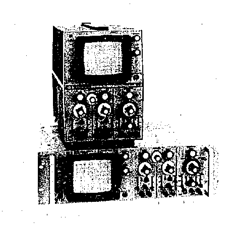
Image 1 of 1
If you have any other photos or manuals for the
Hewlett Packard 1200B
you can
upload the files here.
Equipment:
1200B
Date:
1976
Category:
Group:
Sub Group:
Information
Hewlett-Packard Models 1200A and 1200B Dual Trace
Oscilloscopes are electrically identical, general purpose
instruments. Model 1200A is a cabinet version with a
built-in tilt stand, convenient carrying handle on top, and
feet mounted on both bottom and rear for either bench or
upright operation. Designed primarily for rack mounting, the
Model 1200H uses only 5-1/4 vertical inches of rack space
and has front panel handles for portability.
Since all circuitry is solid state, power consumption is
only about 50 watts, and a cooling fan is not needed.
1 Manual
Service and user manual
Manual type:
Service and user manual
Pages:
112
Size:
6.3 MB
Language:
english
Revision:
Manual-ID:
01200-90904
Date:
November 1976
Quality:
Scanned document, reading partly badly, partly not readable.
Upload date:
Dec. 30, 2017
MD5:
61a9cc60-ad5a-ee2c-8974-42abb02bc1b4
Downloads:
789