Icom - IC-1200A - Transceiver
Manufacturer:
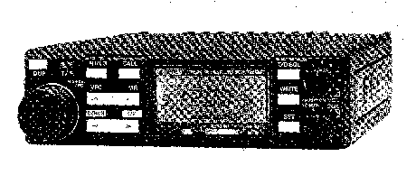
Image 1 of 1
If you have any other photos or manuals for the
Icom IC-1200A
you can
upload the files here.
Equipment:
IC-1200A
Date:
Category:
Group:
Sub Group:
Information
Frequency coverage : 1240 ~ 1300MHz
Frequency resolution : IC-1200A 10 or 20kHz (programmable)
IC-1200E 12.5 or 25kHz (programmable)
Frequency control : CPU based 5kHz (or 6.25kHz) step digital
PLL synthesizer
Simplex and semi-duplex capability (programmable offset)
Memory channels : 21 channels
Usable temperature range : —10°C ~+60°C (+14°F ~+140°F)
Power supply requirement : 13.8V DC ±15% (negative ground)
AC power supply is available for AC operation.
Current drain (at 13.8V DC) : Transmit
HIGH(10W) Maximum 5.5A
LOW (1W) Approx. 2.5A
Receive
Max. audio output Approx. 900mA Squelched Approx. 600mA
Antenna impedance : 50i2 unbalanced
Dimensions : 140(140)mm(W) x 40(40)mm(H) x 196(211 )mm(D)
Bracketed values include projections.
Weight : 1.5kg
■ TRANSMITTER
Output power : HIGH 10W LOW 1W
Emission mode : F3 (F2 when operating with an optional UT-28)
Modulation system : Variable reactance frequency modulation
Max. frequency deviation : ±5.0kHz
Spurious emission : More than 50dB below carrier with high
output power
More than 40dB below carrier with low output power
Microphone : 600£1 electret condenser with push-to-talk and
scanning switches
(IC-1200E: 1750Hz tone call switch)
■ RECEIVER
Receive system : Triple-conversion superheterodyne
Modulation acceptance : FM
Intermediate frequencies : 1st 136.6MHz 2nd 17.2MHz 3rd 455kHz
Selectivity : More than 15.0kHz at —6dB
Less than 30.0kHz at —60dB Sensitivity : Less than 0.22¡jlV
for 12dB SINAD
Audio output : More than 2.4W at 10% distorition with 8i2 load
Audio output impedance : 4 ~ 8£2
• AFC FUNCTION The need to consider frequency drift is over
with the IC-1200A/E
since the transceiver incorporates ICOM's AFC (Automatic
Frequency Control) function. AFC automatically and
conveniently adjusts the frequency the IC-1200A/E receives
to the frequency of the transmitting station.
• COMPACT AND HIGH Smaller and more compact than many
conventional automobile OUTPUT POWER transceivers, the
IC-1200A/E still provides 10W of powerful output
on any frequency in the 1200MHz band.
• SIMPLE PANEL DESIGN Even with so many sophisticated
functions available, the transceiver
front panel layout is extremely simple, making the
IC-1200A/E a mobile unit that is both versatile in
performance and safe to use while driving.
•AUTOMATIC DIMMER A built-in light sensor automatically
adjusts a dimmer circuit to
CIRCUIT control the backlighting of the LCD READOUT. This
feature is
convenient for reducing eye fatigue during night operation.
• 21 MEMORY CHANNELS The IC-1200A/E introduces a large
capacity memory with 21 fully
programmable memory channels, placing a variety of
communications functions at the fingertips of the driver.
• DUAL SCANNING • FREQUENCY SCAN:
FUNCTIONS Searches the entire band continuously with
frequency increments
specified by the operator.
• MEMORY SCAN:
Continuously checks all memory channels.
•SUBAUDIBLE TONE The IC-1200A/E incorporates 38 different
subaudible tones, ensur-
ENCODER ing maximum communications coverage by allowing full
access to
all local repeaters.
•SQUELCH OPTIONS The UT-28 and UT-29 are two new optional
units specially designed
for the IC-1200A/E and are ideal for handling the crowded
band conditions found in many locations.
• UT-28 DIGITAL CODE SQUELCH UNIT:
The UT-28 incorportates a system of digital coding and
decoding, that allows a “personalized” squelch to be
programmed using 1 of 100,000 different code numbers.
• UT-29 TONE SQUELCH UNIT:
The UT-29 is a subaudible tone encoder/decoder that can be
installed as an alternative to the UT-28 Digital Code
Squelch Unit.
1 Manual
Service and user manual
Manual type:
Service and user manual
Pages:
31
Size:
5.2 MB
Language:
english
Revision:
Manual-ID:
A-0885
Date:
Quality:
Scanned document, all readable.
Upload date:
May 14, 2017
MD5:
f068637c-23a9-e68f-82e5-8b7d124bdf67
Downloads:
850