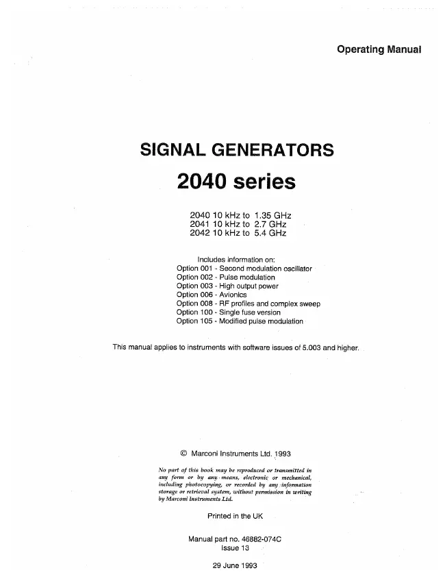
IFR - 2040 - Generator
Manufacturer:

Image 1 of 1
If you have any other photos or manuals for the
IFR 2040
you can
upload the files here.
Equipment:
2040
Date:
1993
Category:
Group:
Sub Group:
Information
The 2040 series of Signal Generators cover the frequency
range 10 kHz to 5.4 GHz with three models: 2040 (10 kHz to
1.35 GHz), 2041 (10 kHz to 2.7 GHz) and 2042 (10 kHz to 5.4
GHz). A dot matrix display with soft key selected screen
options allow flexibility of operation and ease of use. The
output may be amplitude, phase, or frequency modulated with
pulse modulation available as an option. Modulation is
available using a combination of up to two external signal
inputs and a built-in LF source (a second internal source is
optional).
Microprocessor control ensures that the instruments are
flexible and easy to use and allows programming by the
General Purpose Interface Bus (GPIB), The GPIB is designed
to IEEE Standard 488.2 and is a means of sending commands to
an instrument, via a data bus, from a remote controller or
personal computer. The instruments can therefore be used
manually or as part of a fully automated test system.
MAIN FEATURES Operation
Selection of parameters on the screen may involve one or
more of the numeric, hard or soft keys or the rotary knob.
Hard keys have single or dual functions which remain
constant throughout, whereas soft keys have functions
dependent on the present mode of operation. Parameters may
be set to specific values by numeric key entry, while values
may be varied in steps of any size using the if/ll keys or
altered by moving the knob, set to a particular sensitivity.
The SIG GEN, LF, SWEEP, MEM (memory), Δ (delta) and UTIL
(utility) menus are selectable, at any point of operation,
via the keys below the display panel. Within the display,
the soft key functions are indicated by labels which appear
alongside the keys situated at either side of the display panel.
Display
The display is a dot matrix liquid crystal panel, with
backlighting. Carrier frequency, modulation and RF level are
shown in horizontal regions on the principal screen. The
display features 11-digit resolution for carrier frequency,
4-digit for RF level and 3-digit for modulation, with unit
annunciators.
Contrast may be varied, using the control knob, to optimize
the viewing angle. Differing lighting conditions may be
accommodated using the backlight intensity function,
variable from no backlight to full intensity. A full
graphical display test is available, refer to the Service
Manual.
Frequency selection
Carrier frequency is selected via the soft key option on the
SIG GEN display and direct entry via the keyboard.
Alternatively, selection may be made via the General Purpose
Interface Bus (GPIB). Frequency resolution is 0.1 Hz across
the band. Carrier frequencies can be stored in a
non-volatile memory with complete recall when required. An
ON-OFF key is provided to completely disable the output
Output
RF output up to +13 dBm can be set by direct keyboard entry
with a resolution of 0.1 dB or better over the entire range.
A high output option is available to extend the maximum
calibrated level to +19 dBm on the 2040 instrument.
An extended hysteresis facility allows for extended
electronic control of RF output level without introducing
mechanical attenuator transients when testing squelch systems.
A low intermodulation mode can be selected which disables
the RF levelling system and improves the intermodulation
performance when combining the outputs of two signal generators.
A choice of calibration units is available to the operator
and provision is made for the simple conversion of units
(for example, dBm to μν). Calibration data for the output
level is held in memory and may be altered from the front
panel or over the interface bus.
The output level can be offset by up to ±2 dB by keyboard
entry. Offsets from the calibrated value may be used to
compensate for cable or switching losses external to the
generator. This facility can be used as a means of
deliberately offsetting the output level to ensure that all
generators in an area give identical measurements. While
using the offsetting facility, the principal calibration of
the generator is not lost and may be returned to at any time.
An electronic trip protects the generator output against
reverse power of up to 50 W, preventing damage to output
circuits when RF or DC power is accidently applied.
1 Manual
User manual
Manual type:
User manual
Pages:
136
Size:
4.9 MB
Language:
english
Revision:
Issue 13
Manual-ID:
46882-074
Date:
Quality:
Scanned document, all readable.
Upload date:
May 24, 2015
MD5:
3afc2501-c288-9304-13a1-7baa85c85579
Downloads:
1489
