Iwatsu - SS-5711 - Oscilloscope
Manufacturer:
Image 1 of 2
If you have any other photos or manuals for the
Iwatsu SS-5711
you can
upload the files here.
Equipment:
SS-5711
Date:
Category:
Group:
Sub Group:
Information
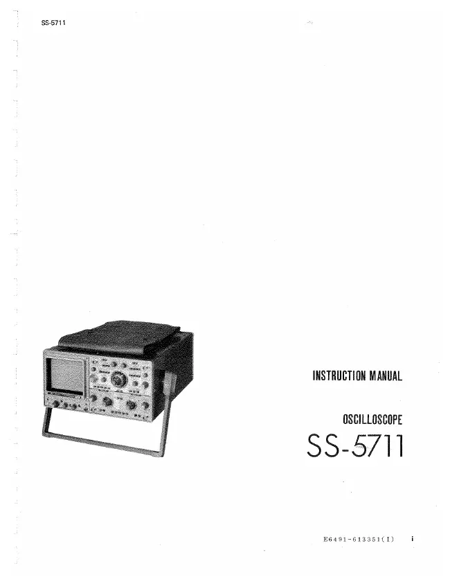
The 55-5711 is an oscilloscope with a frequency bandwidth
of DC to 100 MHz that can display 8 traces on 4
channels.
The SS~5711 is useful in a wide range of applications for
not only production lines and maintenance and service
purposes but also for the research and development of a
variety of electronic devices. The features of the SS-5711
are as follows:
'In addition to display of 8 traces on 4 channels. the SS-5711
has an ADD function for measuring the sum of two signals
and CH 2 POLAR for measurement of the difference between
two signals.
• Both CH 1 and CH 2 have a high deflection factor of 1
mV Idiv (in the x5 MAG function). which permits accurate
measurement of voltages.
· The horizontal deflection system has sweep rates up to
2 nsec/div (in the xl0 MAG function Iso that even highspeed
phenomena can be measured with accuracy.
• The SS-5711 has delayed sweep. single sweep. AL T
sweep, and X-V operation functions, and a TV synchronizing
signal separator circuit so that television and other
composite video signal waveforms can be observed.
1 Manual
Service manual
Manual type:
Service manual
Pages:
196
Size:
11.4 MB
Language:
english
Revision:
Manual-ID:
Date:
Quality:
Scanned document, all readable.
Upload date:
May 14, 2015
MD5:
dbfa5b52-cce4-7dd2-3fb7-1d2defc1b1a3
Downloads:
1214