
Keithley - 7059 - Interface
Manufacturer:
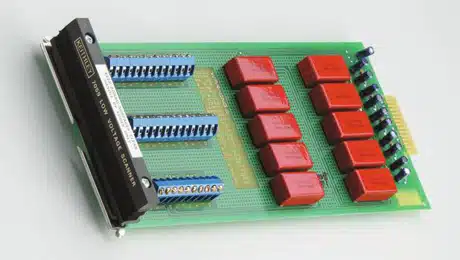
Image 1 of 2
If you have any other photos or manuals for the
Keithley 7059
you can
upload the files here.
Equipment:
7059
Date:
1989
Category:
Group:
Sub Group:
Information
The Model 7059 is a low voltage scanner plug-in card which
is field-installable in the Model 705 and Model 706 scanner
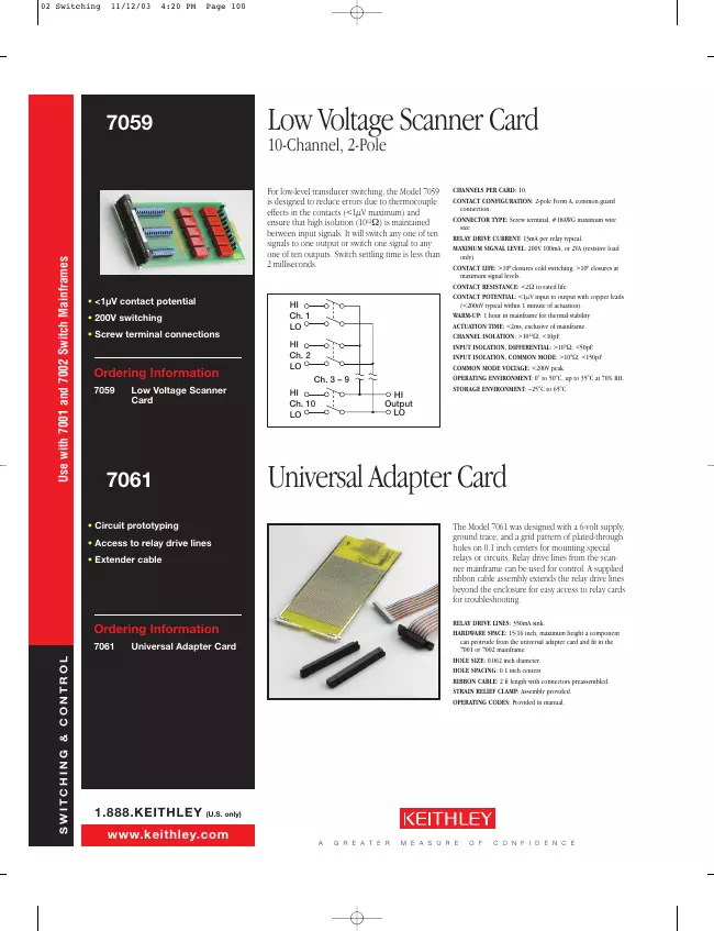
mainframes. The Model 7059 will switch up to 10 channels.
For low-level transducer and thermocouple output switching
the Model 7059 is designed to introduce a minimum of thermal
voltage error ( < 1µV input to output with copper leads),
and ensure that high isolation (10¹²Ω) is maintained between
input signals. Expected relay life (10⁶ closures) is
obtained when signals less than 10V or 10mA are switched.
However, peak signals up to 200V or 100mA may be switched
with the scanner, Quick disconnect screw terminals are used
to facilitate input and output connections to the scanner
plug-in card (relay cardl. The plug-in card is easily
removed through the rear panel of the scanner mainframe.
2 Manuals
Service and user manual
Manual type:
Service and user manual
Pages:
19
Size:
428.7 KB
Language:
english
Revision:
E
Manual-ID:
7059-901-01
Date:
Quality:
Scanned document, all readable.
Upload date:
March 2, 2014
MD5:
d4f1f004-9da5-4d8f-2ad5-2b051f2acdc7
Downloads:
498
Datasheet
Manual type:
Datasheet
Pages:
1
Size:
483.2 KB
Language:
english
Revision:
Manual-ID:
Date:
Quality:
Electronic document, no scan, very well readable.
Upload date:
March 7, 2014
MD5:
e50e5963-5b9c-8400-2311-25434185036b
Downloads:
730