Krohn-Hite Corporation - 4500 - Oscillator
Manufacturer:
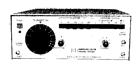
Image 1 of 1
If you have any other photos or manuals for the
Krohn-Hite Corporation 4500
you can
upload the files here.
Equipment:
4500
Date:
Category:
Group:
Sub Group:
Information
The Krohn-Hite Model 4500 is an ultra-low distortion, stable
amplitude oscillator designed for test and measurement
applications in the 1Hz to 100kHz frequency range.
The 4500 produces a virtually "distortion free" (<0.001%)
sinewave for measuring harmonic distortion in audio
pre-amplifier and power amplifier circuits. It also
generates squarewaves with aberrations of less than 5% peak
to peak amplitude. The exceptionally flat response of the
4500 (+0.05dB) eliminates the need to constantly monitor
voltage levels during amplifier response tests.
The unit delivers up to 7 volts rms open circuit to MAIN and
INVERTED OUTPUTS of 600 ohm impedance. A MAIN OUTPUT of 50
ohms impedance is also provided. A four position pushbutton
ATTENUATOR calibrated in 20dB steps together with a 30dB
vernier provides a total dynamic range of 90dB. Amplitude
and frequency stability varies less than 0.001% with a 10%
change in line voltage.
Sumultaneous INVERTED (180°) OUTPUT is provided for
synchronizing a scope or as an auxiliary output. The output
is fixed at 7 volts rms from a 600 ohm source impedance.
Frequency tuning is provided by a 10:1 tuning dial and a 5
band decade multiplier .
When combined with Krohn-Hite' s Ultra-Low Distortion
Analyzer 6800A/6900 Series, it provides a complete
distortion measurement system.
1 Manual
Service and user manual
Manual type:
Service and user manual
Pages:
24
Size:
863.9 KB
Language:
english
Revision:
Manual-ID:
Date:
Quality:
Scanned document, all readable.
Upload date:
Sept. 6, 2015
MD5:
7196c977-06be-da56-9312-3e14a0f46158
Downloads:
675