Marantz - 3800 - System Controller
Manufacturer:

Image 1 of 2
If you have any other photos or manuals for the
Marantz 3800
you can
upload the files here.
Equipment:
3800
Date:
Category:
Group:
Sub Group:
Information
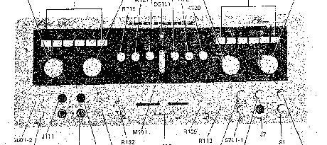
High-and low-level inputs (program sources) are
selected by the Program Selector Pushswitches
and applied in accordance with signal level.
When low-level sources are selected (PHONO or
MIC), the Program Selector Pushswitch applies
the input signal to the Phono/Mic Amplifier
circuit and selects the proper equalization,
RIAA or Mie. The output of the Phono/IVlic
Amplifier is then returned to the Program
Selector Pushswitches where it is handled as
another high-level input.
High-level input signals TUNER, AUX, TAPE 1,
TAPE 2 or the output of the Phono/Mic An plifier
are applied to the Dolby encoder/decoder
1-1
through the buffer amplifier circuit, TAPE
REC-EQand DOLBY Switches. The input level
to the encoder/decoder is regulated by the
RECORD LEVEL Controls. The output of the
encoder/decoder is applied to the TAPE OUTPUT
and DUBBING OUT Jacks. With the
DOLBY Switch set to OFF, the encoder/decoder
is bypassed and the high-level input signals are
applied directly to the TAPE OUTPUT and
DUBBING OUT Jacks. The encoder/decoder
functions as a flat amplifier, an encoder, or a
decoder depending on the position of the
DOLBY Switch (Figures 1-1 and 3-9).
The high-level input signals are concurrently
applied to the SCOPE OUTPUT Jacks and to the
Dolby decoder, through the TAPE MONITOR
Switch and PLAY CAL Controls. The decoder
functions as a flat amplifier, or a decoder, depending
on the position of the DOLBY Switch,
the TAPE MONITOR Switch, and the TAPE
COPY Switches (Figure 1-1). The output signal
ofthe decoder is monitored by the Dolby Level
VU Meter and applied to the MODE Switch.
The MODE Switch determines the manner in
which the left- and right-channel signals of the
program source are applied in the Model 3800:
LEFT channel only, RIGHT channel only, twochannel
STEREO, STEREO REVERSE, or
L + R (left and right channels combined). The
signal selected by the MODE Switch is then
applied to the BALANCE Control. The
BALANCE Control adjusts the relative signal
level of the left and right channels by attenuating
the level of one channel while maintaining the
level of the other. From the BALANCE
Control, the signal is applied to the VOLUME
Control, which varies the level of the output
signal available at the PREAMPLIFIER OUTPUT
Jacks.
The signal is also applied to the Loudness
Contour Circuit which, when activated, boosts
low and high frequencies at low listening levels
so that all frequencies appear to have equal
loudness. The Loudness Contour Circuit adjusts
the frequency response of the Model 3800 to
compare with the Fletcher-Munson loudness
curves (Section 2). The signal from the
VOLUME Control is then applied to the input
of the Times-Ten (X10) Amplifier Circuit.
The X10 Amplifier increases the signal level to
that required to drive power amplifiers. The
output of the X10 Amplifier is applied to an
Active Filter Network comprised of three filter
circuits (30Hz, 5KHz and 9KHz) and a Filter
Amplifier. The Active Filter Network sharply
reduces low- and/or high-frequency noise that
may originate at the program source. The output
ofthe Filter Amplifier is then applied to the
Tone Control/Turnover Network (BASS, MID
and TREBLE Tone Controls), the 250Hz and
the 4KHz TURNOVER circuitry, and a Tone
Amplifier stage (through the TAPE REC-EQ
Switch). The output of the Filter Amplifier
after TAPE REC-EQ is also applied to the
TONE DEFEAT Switch.
The Tone Control/Turnover Network performs
a dual function: the tone control portion of
the network boosts or attenuates low, middle
and high frequencies; the turnover portion of
the network, when activated, decreases the
point at which low frequencies are affected by
the BASS Control (250Hz) and increases the
point at which high frequencies are affected by
the TREBLE Control (4KHz). The TONE
DEFEAT Switch selects either the flat output
of the Filter Amplifier (bypassing the tone
controls) or the tone-control-altered output of
the Tone Amplifier. From the TONE· DEFEAT
Switch, the signal is applied to the Time Delay
Relay.
The circuit associated with the Time Delay
Relay holds.the relay contacts open for approximately
five seconds after power is applied to
the Model 3800. After the power supply
circuits have stabilized, the relay contacts close.
Audible “ pops" that may arise from power
supply transients are thereby eliminated.
From the relay contacts the signal is applied to
the PREAMPLIFIER OUTPUT Jacks and connected
to drive an external power amplifier.
The power amplifier outputs are connected to
the SPEAKER SWITCHING INPUTS Terminals
and the signal is applied to the stereo PHONES
2 Manuals
Service manual
Manual type:
Service manual
Pages:
49
Size:
12.5 MB
Language:
english
Revision:
Manual-ID:
Date:
Quality:
Scanned document, all readable.
Upload date:
May 29, 2016
MD5:
5fa8df6d-b46c-8a62-7383-bf94ad6adedb
Downloads:
612
Service manual
Manual type:
Service manual
Pages:
49
Size:
12.5 MB
Language:
english
Revision:
Manual-ID:
Date:
Quality:
Scanned document, all readable.
Upload date:
May 29, 2016
MD5:
96beaf2b-1c0a-924b-ae9d-33d49ec79695
Downloads:
557

