Marconi - 2300A - Level Meter
Manufacturer:
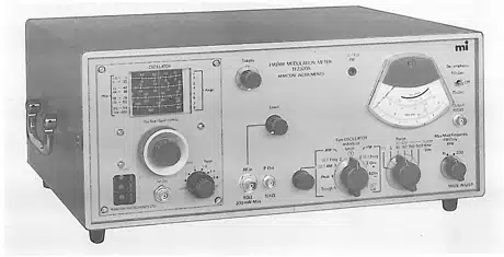
Image 1 of 1
If you have any other photos or manuals for the
Marconi 2300A
you can
upload the files here.
Equipment:
2300A
Date:
1974
Category:
Group:
Sub Group:
Information
The TF 2300A Modulation Meter is primarily for measurement
of f. m. deviation but it also measures a. m. depth. With
its wide range of deviation frequency, modulation bandwidth
and carrier frequency, this instrument is suitable for
application to fixed and mobile point-to-point
communications, broadcasting, telemetry and multi-channel
link equipment in the h. f. , v. h. f. and u. h. f. bands.
Distortion and channel separation tests on f. m. stereo
receivers and transmitters can also be made.
Positive and negative f. m. deviation can be measured in
ranges from 1. 5 kHz to 500 kHz full- scale at modulation
frequencies between 30 Hz and
3.4 kHz on the 1. 5 kHz deviation range, and 30 Hz and 200
kHz on all other deviation ranges. A. M. depth can be
measured up to 95% in a 30 Hz to 15 kHz modulation
bandwidth. Either f. m. or
a. m. can be measured in the presence of the other. Although
measurements are normally made by means of the meter
readout, i. f. and demodulated outputs are available at the
front panel for examination or analysis.
Spurious a.m. and f. m. due to hum and noise are kept to a
level insignificant for most applications but, where
required, crystals can be switched in to control the local
oscillator, or an external local oscillator may be used. The
instrument can be operated without a local oscillator for
measurements in the 1-2 MHz range.
The instrument can be operated from mains power or a nominal
24 V battery. Voltage regulation eliminates transformer tap
changing except between 115 V and 230 V ranges. On battery,
the regulation compensates for battery voltage variations
between 21.5 and 30 V. Transistorized circuits consuming
little current give reasonable length of operation
onbatteryfor mobile purposes.
1 Manual
Service and user manual
Manual type:
Service and user manual
Pages:
90
Size:
28.4 MB
Language:
english
Revision:
Manual-ID:
Date:
Quality:
Scanned document, all readable.
Upload date:
Feb. 20, 2016
MD5:
64c4df8f-29ba-8c07-83c6-6a9183d4b256
Downloads:
736