Marconi - 2305 - Level Meter
Manufacturer:

Image 1 of 2
If you have any other photos or manuals for the
Marconi 2305
you can
upload the files here.
Equipment:
2305
Date:
1982
Category:
Group:
Sub Group:
Information
1. 2305 is a high performance, microprocessor controlled,
modulation meter with a comprehensive specification covering
the carrier frequency range
50 kHz to 2.3 GHz.
2. Operation may be either local or remote. Local control is
obtained via functionally grouped key switches which form
the front panel controls and which direct all the instrument
functions except those of SUPPLY ON and LF
LEVEL.
3. Indication of measured quantities is provided by two
l.c.d. 7-segment digital displays : frequency - either of
the carrier or of the modulating tone - appears in the
8~digit left-hand display, modulation - in % a.m., kHz or
radians deviation — appears in the 4 digit right-hand display.
4. The microprocessor allows maximum flexibility in
arranging and controlling the circuit functions and permits
remote operation via the GPIB* when the instrument is fitted
with the GPIB interface optional accessory. The 2305
is thus as well suited for stand-alone manual operation as
for incorporation in automatic systems with programmed
operation and makes few demands on operator skill.
5. In it* simplest method of operation, the 2305 provides
both automatic tuning and control of the ranging circuits,
although tuning may be controlled directly by keypad entry
of numerical data, and individual ranges may be retained by
the use of keyboard second functions"1’ if necessary. A HOLD
ON/OFF key permits all ranges and functions to be locked in
their present states.
6. In both forms of tuning, the local oscillator frequency
retains the same sense relationship with signal frequency
needed to ensure that positive frequency and phase
excursions are always presented as P+,
7. In the CARRIER ERROR mode the instrument will measure
small frequency drifts or offsets by continuously
subtracting a stored reference value from instantaneous
measurements of the carrier. The reference value can be
either a numerical entry made via the keypad or a particular
instantaneous measurement transferred to store by operation
of the CARRIER ERROR key. Two other frequency measurement
modes provide for the display of either carrier or
modulating frequency.
8. When necessary, an external 10 MHz standard may be used
in place of the internal reference which forms the basis for
local oscillator frequency synthesis and for frequency
measurement. It is also possible to provide for direct
substitution of the local oscillator signal by a source of
external origin. The changeover in both cases being effected
by second function keying.
9. Modulation is normally measured as peak excursions of
either the amplitude, frequency or phase of the carrier
signal and a choice of detector modes enables the peaks of
each polarity either to be measured separately or for their
average to be calculated and presented as Two additional
detector modes offer (1) an averaging detector, and (2) a
PEAK HOLD function. The averaging mode (NOISE AVG) is useful
when noise is to be measured, and the quantity displayed
when in this mode is of the peak value of a sine wave having
the same average value. In PEAK HOLD, successive peak
samples are examined and store and display are up-dated
each' time the previous largest sample is exceeded.
The PEAK HOLD mode is useful for logging transients and
other aspects of modulator system performance under
operational conditions. In the a.m. mode, peaks are always
measured as P+ and troughs as P- .
10. The 2305 will tune and measure automatically without
loss of accuracy on signal levels be tween - 18 dBm and +30
dBm. The sensitivity increases considerably towards the
bottom end of the frequency range and a substantial further
increase can be obtained by reverting to manual tuning.
Input protection is provided above the permitted maximum of
+30 dBm. Deep amplitude modulation may reduce the signal
level during troughs to a point that is insufficient to
ensure proper functioning of the internal frequency counter
and auto-tuning may be adversely affected. The effect is
only likely to occur with a.m. greater than 90% and, if it
happens, the a.m. depth should be temporarily reduced to
allow auto-tuning to complete.
11. Frequency deviation can be measured up to a maximum of
500 kHz for modulation frequencies up to 275 kHz. The
accuracy attainable varies with modulation frequency and
approaches ±0.5% at 1 kHz.
12. Phase deviation can be measured to a maximum of 500
radians up to ] kHz modulation frequency. Above this
frequency the maximum measurable deviation decreases at 6 dB
per octave.
13. Amplitude modulation up to 95% can be measured with
accuracies approaching 1%, depending on modulation depth and
frequency, up to a maximum modulation frequency of 50 kHz.
Useful indications are given for depths up to 99.9%.
14. Measurements of all three types of modulation can be
related to any reference level and expressed as dB. The
reference quantity may be entered numerically via the keypad
or may be a measurement selected from a series and
transferred to store by a single key stroke.
15. The post detector bandwidth may be shaped by any one of
five built-in filters which cover the varied requirements cf
mobile radio, broadcasting, telemetry etc. There is also a
choice of 3 de-emphasis time constants which may be
introduced into the audio output signal in f.m. mode. They
may also be introduced into the measurement system by a
keyboard second function. External filters may be introduced
into the measurement circuit in addition to and
independently of any internal selection.
16. Standards of amplitude and frequency modulation are
generated within the instrument for calibration purposes.
The 2305 automatically runs a selfcheck routine against
these standards after each switch-on and displays pass/ fail
data. 2305 measurements can be recalibrated against these
standards at any time by operation of the CAT key.
17. For systems use or production tests, up to 10 sets of
control settings may be stored in non-volatile memory for
subsequent recall and use.
18. In its POWER function, the 2305 will normally display
the power entering the input terminal in dBm or watts. The
measurement is based on peak voltage detection and will
indicate peak power on amplitude modulated signals. The
range may be extended upward by added external attenuation
and a flexible system of power calibration with optional
display in watts or dBm can be introduced by second functions.
2 Manuals
Service and user manual
Manual type:
Service and user manual
Pages:
70
Size:
2.4 MB
Language:
english
Revision:
2
Manual-ID:
Η 52305-900Κ
Date:
Quality:
Scanned document, all readable.
Upload date:
Feb. 20, 2016
MD5:
c9ea1801-68c2-4ae4-7fc7-06ffab03a7a9
Downloads:
862
Service and user manual
Manual type:
Service and user manual
Pages:
226
Size:
2.9 MB
Language:
english
Revision:
Manual-ID:
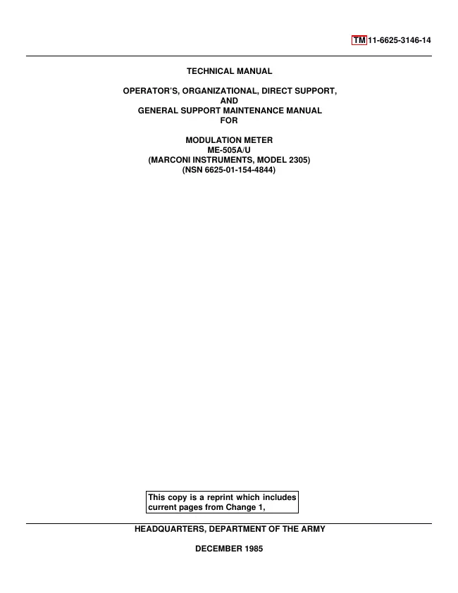
TM 11-6625-3146-14
Date:
December 1985
Quality:
Scanned document, all readable.
Upload date:
Jan. 6, 2019
MD5:
0a83cc8a-c672-5cc4-96e8-1c1343e48299
Downloads:
332

