Marconi - TF 2337A - Level Meter
Manufacturer:
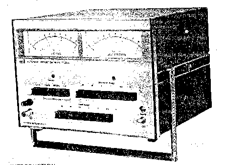
Image 1 of 1
If you have any other photos or manuals for the
Marconi TF 2337A
you can
upload the files here.
Equipment:
TF 2337A
Date:
1976
Category:
Group:
Sub Group:
Information
The TF 2337A Automatic Distortion Meter enables rapid and
accurate measurement of both level and distortion,factors of
audio frequency signals. The need to tune tor fundamental
frequency rejection is avoided, thus operation simply
consists of the selection by push button switches of the
input voltage range, distortion range and fundamental frequency.
The instrument measures distortion in the conventional way,
that is, by filtering out the fundamental component and
comparing the residual with that of the total signal.
However, because of the novel design of the ratio circuit
the need for reference level adjustment prior to distortion
measurement is obviated. Thus fluctuations of the input
level (up to -10 dB) will not affect the accuracy of the
distortion measurement.
The TF 2337A is therefore suitable for repetitive distortion
measurements and because of its simplicity of operation is
ideal for factory testing of mass production units such as
a. f. amplifiers etc. Furthermore as the instrument employs
a multi-stage Twin-'Γ active filter having a fairly wide
rejection band (66 dB at-+5% of fo), the affect of wow and
flutter on the distortion measurement is negligible.
This attribute is particularly useful for t. h. d.
measurements of output signals on equipment such as tape
recorders and record players.
Owing to the use of field effect transistors in the input
stage, internal noise is low and therefore with input
signals as low. as 10 mV, distortion can be measured down to
0. 01%.
1 Manual
Service and user manual
Manual type:
Service and user manual
Pages:
40
Size:
1.8 MB
Language:
english
Revision:
Manual-ID:
Date:
Quality:
Scanned document, reading partly badly, partly not readable.
Upload date:
May 28, 2016
MD5:
5ea122a1-d1a7-3f51-2b53-b40824fa8787
Downloads:
718