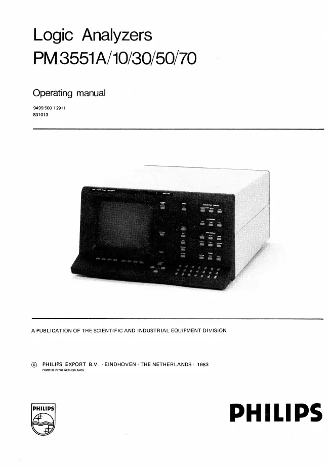
Philips - PM3551A/70 - Logic Analyzer
Manufacturer:

Image 1 of 1
If you have any other photos or manuals for the
Philips PM3551A/70
you can
upload the files here.
Equipment:
PM3551A/70
Date:
1983
Category:
Group:
Sub Group:
Information
The PM3551A/70 is capable of recording a maximum of 59 state
channels and 8 50MHz timing channels while the PM3551A/30
although identical in design and operation is capable of
measuring a maximum of 35 state channels and 8 50MHz timing
channels.
The PM3551A/10 and PM3551A/50 have the same features as the
above mentioned PM3551A/30 and PM3551A/70 models with the
exception of the "50MHz Timing Analyzer*' mode.
The operator control panel is divided into several
functional areas which guide and help the user to set up the
most effective test procedure.
A functionally organized keyboard/softkey structure in
combination with an interactive menu-display serve the user
in setting up and entering parameters for triggering,
capturing, comparing and counting the activities of the
system under test.
The extensive triggering capability of the 7 sequential
trigger-words, that can be combined with clock and
trigger-qualifiers, permits capturing data from complex
system activities or from deep branched or nested loops.
Each trigger-word has the same width as the number of input
channels of the various models.
The sequence of the different trigger-words used can be
defined by the use of an IF, THEN, ELSE algorithm, with the
possibility of placing a certain amount of delay between the
statements.
In this mode triggering can be selected as True or False.
A notable feature of this mode is that the selected trigger
sequence can be specified as true or alternatively as not
true. This latter mode is called "Trigger on Sequence Break"
mode and provides the capability of triggering when a
defined repetitive pattern (eg. a loop or a polling
sequence) is broken or not executed in the specified order.
The moment of capturing data can be delayed by states and/or
trigger occurrences and/or time.
The Logic Analyzer can also be used for making time
measurements *
A readout of the elapsed time between two points in a
program can be obtained.
Special features of note here are the COMBI and the SYNC modes.
The COMBI mode allows the state section to be triggered by
the timing section or vice-versa, while in the SYNC mode the
displays of a number of timing channels are cross-referenced
with state sampling. This enables analysis of critical
state/time relationships.
Data to be captured is clocked into the analyzer on selected
clock edges of one of the three selectable clock sources.
For each clock used, there are up to four qualifiers available.
In the COMPARE mode, a comparison can be made between
captured data and stored data in the formats: List or Timing.
The instrument automatically stores the current mode- and
function instrument-setting, when the mains voltage supply
is switched off.
After switching on, the instrument comes up in the initial
default mode- and function setting.
All analyzer models can be equipped with the option
(non-volatile memory) to store up to 4 additional settings.
Here each setting is stored and retrieved under a label.
In the TIMING mode, glitches of a duration of as little as 5
nanoseconds can be captured from the data-stream.
The PM 3551A can be equipped with a 4 channel 300MHz timing
option, independently of the presence of the 8 channel 50
MHZ section.
This allows high precision timing measurements.
Other options are the options board with standard RS232C
printer output. This board can be equipped with an GPIB
control interface, or a RS232C control interface, both
providing full remote control of the instrument.
The options board is also a prerequisite for installation of
disassembly- packages, and the non-volatile setting memory.
The disassembly-packages allow the user to view captured
data in the mnemonic language of the most currently
available 8 and 16-bit microprocessors•
Data is entered into the analyzer via 8-channel pods, each
provided with its own threshold adjustment. A variety of
convenient Pod-attachments are available for connecting the
system under test to the analyzer.
A comprehensive built-in diagnostic program can be used as
an aid to test the various functions of the analyzer and to
assist in fault-finding.
1 Manual
User manual
Manual type:
User manual
Pages:
202
Size:
19.0 MB
Language:
english
Revision:
Manual-ID:
9499 500 12911
Date:
October 1983
Quality:
Scanned document, all readable.
Upload date:
Jan. 29, 2017
MD5:
018d62b7-3d89-e31c-43ae-a1a17bf4f7fc
Downloads:
1966
