Racal - 1998 - Frequency counter
Manufacturer:
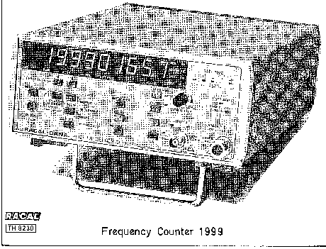
Image 1 of 2
If you have any other photos or manuals for the
Racal 1998
you can
upload the files here.
Equipment:
1998
Date:
1993
Category:
Group:
Sub Group:
Information
INTRODUCTION
1 The Racal-Dana frequency counters Models 1998 and 1999 are
microprocessor-controlled instruments offering high-accuracy
measurements with a comprehensive range of facilities.
MEASURED FUNCTIONS
Frequency A Function
2 The Frequency A function is used to measure the frequency
of the signal applied to the channel A input. A resolution
of nine digits is available with a one-second gate time.
Frequency B Function
3 The Frequency B function is used to measure the frequency
of the signal applied to the channel B input. A resolution
of nine digits is available with a one-second gate time.
Period A Function
4 The Period A function is used to measure the period of the
waveform applied to the channel A input. A number of
periods, depending upon the resolution (and therefore the
gate time) selected, are measured, and the average value is
displayed.
Ratio A/D Function
5 The Ratio A/D function is used to measure the ratio of the
frequency applied to the channel A input to that applied to
the channel D input.
Ratio B/A Function (1998 Only)
6 The Ratio B/A function is used to measure the ratio of the
frequency applied to the channel B input to that applied to
the channel A input.
CHECK FUNCTION
7 With the Check function selected a number of functional
tests of the instrument’s circuits can be made without the
use of additional test equipment. Although these tests do
not check the instrument's performance to its published
specification, they can be used to verify that the equipment
is operating correctly. A suitable functional check
procedure is given in Section 3.
SIGNAL INPUT CHANNELS
8 Signal input channels A and B are fully independent.
9 Channel A is provided with controls to permit the
selection of:
(1) 1 ΜΩ or 50 Ω input impedance.
(2) Input attenuation continuously variable from 0 dB to
approximately 58 dB using the ATTN (X20) and SENSITIVITY
controls.
(3) 50 kHz low-pass filter.
(4) Pulse offset (trigger level) to cater for signals of
various duty cycles.
10 Channel B has a 50 Ω input impedance. On the 1998 the
input is fuse- protected for signals above 7 V. On the 1999
the input is protected by an internal attenuator for signals
above 4 V.
ERROR INDICATION
11 Certain errors in the operation of the instrument will
result in the generation of error codes, which will be
displayed. Details are given in Section 4 of this manual.
EXTERNAL ARMING
12 External arming of the start circuit for the measurement
interval can be carried out by means of signals connected to
a BNC connector mounted on the rear panel.
DISPLAY
13 A 10-digit numeric display with units annunciators is
used. Indicators are provided to show when overflow of the
most significant digit occurs, and to show the measurement
interval (gate time).
HOLD FEATURE
14 The hold feature allows readings to be held indefinitely.
A new measurement cycle is initiated using the RESET key.
RESOLUTION AND GATE TIME
15 The gate time is determined by the display resolution
selected. Details of the relationship between gate time and
display resolution for each measurement mode are given in
Section 4 of this manual.
GATE OUTPUT
15 The internally-generated gate signal is available at a
pin on the rear panel. The gate output will be delayed
relative to the internal measurement gate by 10 nsec
typically (15 nsec maximum).
17 When used in the single-shot mode, the gate waveform
comprises a short trigger pulse, followed by a hold-off time
of about 1 ms followed by the measurement gate waveform
proper; this is to allow the external circuit output to
stabilise after triggering.
EXTERNAL FREQUENCY STANDARD INPUT
18 The instrument may be operated using an external
frequency standard. The instrument will operate from the
external standard, in preference to the internal standard,
whenever the signal at the EXT STD INPUT socket is of
sufficient amplitude. It will revert to operation from the
internal standard automatically if the input from the
external standard is removed.
STANDBY MODE
19 When the instrument is switched to standby, the internal
frequency standard continues to operate and the instrument
status is maintained but the measuring circuits are switched
off. If the battery pack option is fitted and an external
power supply is connected, the battery is charged at the
full rate.
NULL FUNCTION
20 With the NULL function active the instrument displays the
difference between the measured value and the value held in
the internal NULL store.
INITIALIZATION
21 When the instrument is first switched on, or when it is
initialised via the GPIB, it is set to the following conditions:
Measurement Function FREQ A
Display Resolution 8 digits (0.1 second gate time)
Channel A Input 1 ΜΩ input impedance
No trigger offset ( )
LF filter disabled XI attenuation
Null Function Disabled
Null Store 0
External Arming Disabled
Hold Function Disabled
OPTIONS AVAILABLE
Frequency Standards (04X Options)
22 A wide range of internal frequency standard options is
available. The technical specifications are given in Section
1 of this manual. The frequency standard can be changed, if
required, by the customer: instructions are given in Section 3.
Reference Frequency Multiplier (Option 10)
23 The reference frequency multiplier is an
internally-mounted, phase- locked multiplier, which permits
the use of external frequency standard signals at 1 MHz, 2
MHz, 5 MHz or 10 MHz. The multiplier can be fitted by the
customer: instructions are given in Section 3.
GPIB Interface (Option 55)
24 An internally mounted interface to the IEEE-488-GPIB is
available. This permits remote control of all the
instrument's functions except the power ON/OFF switching,
the standby switching, and the channel A sensitivity
potentiometer setting. The interface can be fitted by the
customer: instructions are given in Section 3. The GPIB
interface cannot be fitted to an instrument already fitted
with the battery pack option. An adapter, Racal-Dana part
number 23-3254, to convert the connector to the I EC 625-1
standard is available as an accessory.
Battery Pack (Option 07)
25 Fitting the internal Battery Pack Assembly permits the
instrument to be used in locations where no suitable AC
supply is available. The option also allows operation from
an external DC supply.
26 The battery is trickle-charged whenever the instrument is
operated from an AC supply and the internal/external switch
is at INTERNAL BATTERIES. Charging at the full rate is
carried out when the instrument is switched to the standby
mode and connected to an external AC or DC supply. A full
charge requires approximately
14 hours.
27 The instrument will operate continuously from a
fully-charged battery for approximately 4.5 hours (1998) and
3.75 hours (1999). It will switch off automatically when the
battery reaches the discharged condition. The STBY/CHRG
indicator starts to flash approximately 15 minutes before
this occurs. The battery life can be extended by use of the
Battery-Save facility.
28 The battery pack can be fitted by the customer.
Instructions are given in Section 3. When using the GPIB
interface option the battery pack cannot be fitted.
Rack Mounting Kits
29 The following kits permitting the instrument to be
mounted in a standard 19-inch rack are available:
(1) Single instrument, fixed-mount kit (Option 60A).
(Racal-Dana part number 11-1648).
The mounted instrument occupies half the rack width and is
two rack units (3.5 inches) in height. The instrument is
mounted offset in the rack and may be at either side.
(2) Double instrument, fixed-mount kit (Option 60B).
(Racal-Dana part number 11-1649).
The panel of the mounting kit occupies the full rack width
and is two rack units (3.5 inches) in height. Two
instruments can be mounted side-by-side.
30 All the kits can be fitted by the customer. Instructions
are given in Section 3.
1 Manual
User manual
Manual type:
User manual

Pages:
74
Size:
1.7 MB
Language:
english
Revision:
Manual-ID:
ΤΗ 8230
Date:
Quality:
Scanned document, all readable.
Upload date:
Oct. 25, 2015
MD5:
bafd477e-b3dc-400d-51a5-ff737de4238c
Downloads:
1103