Systron Donner - 7004 - Digital multimeter
Manufacturer:
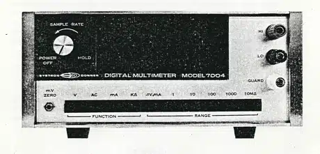
Image 1 of 1
If you have any other photos or manuals for the
Systron Donner 7004
you can
upload the files here.
Equipment:
7004
Date:
1972
Category:
Group:
Sub Group:
Information
The SD.Model 7004 Digital Multimeter is a full four-digit precision instrument. It offers the five selectable functions of dc voltage, dc current, ac voltage, ac current and resistance. The instrument utilizes an advanced Dual-Slope Integration design with an extremely low-noise input amplifier and a fully guarded, isolated input circuit. These features combine to provide high accuracy and stability, plus exceptional immunity to the effects of both common mode and normal mode noise.
Ail function and range selection is made from front-panel pushbutton controls. The readout features a nonblinking display of four full digits plus overrange, auto-positioned decimal point, and an indicator for off-scale readings. Polarity indication for dc voltage and current is automatic with, a minus indicator display.
Model 7004 is light-weight and completely portable. It consumes less than 8 watts while operating at line frequencies from 48 to 440 Hz and at voltages of 115/230 V or 100/200 V.
The Multimeter may be fitted with an optional built-in battery pack with no increase in size. Optional DTL/TTL compatible digital outputs can also be included for remote printout, digital limit comparison, or other automatic data system requirements .
1 Manual
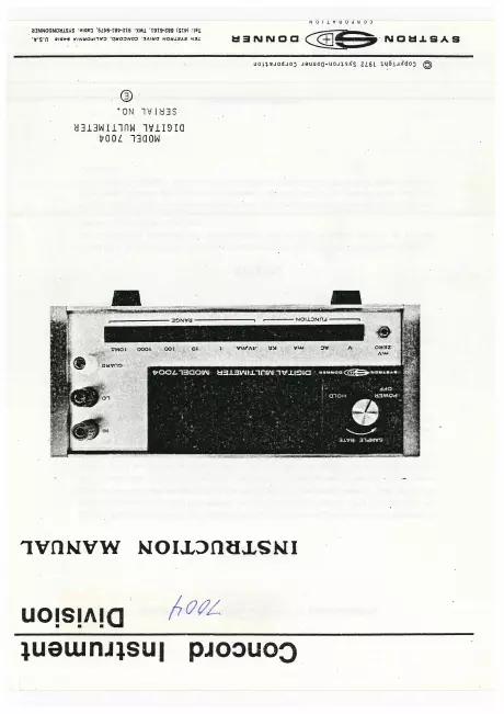
Service and user manual
Manual type:
Service and user manual
Pages:
97
Size:
39.8 MB
Language:
english
Revision:
Manual-ID:
Date:
January 1972
Quality:
Scanned document, reading partly badly, partly not readable.
Upload date:
Oct. 5, 2019
MD5:
e330ef37-4f8a-ca84-02a0-a1aa2c3a205d
Downloads:
405