Tektronix - TDS 640A - Oscilloscope
Manufacturer:
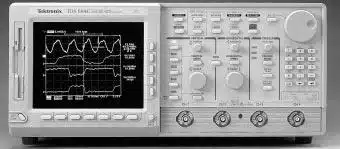
Image 1 of 1
If you have any other photos or manuals for the
Tektronix TDS 640A
you can
upload the files here.
Equipment:
TDS 640A
Date:
1993
Category:
Group:
Sub Group:
Information
The TDS 620A, 640A, & 644A are portable, four-channeldigitizing oscilloscopes suitable for use in a variety of test and measurement applications
and systems.
Key features include:
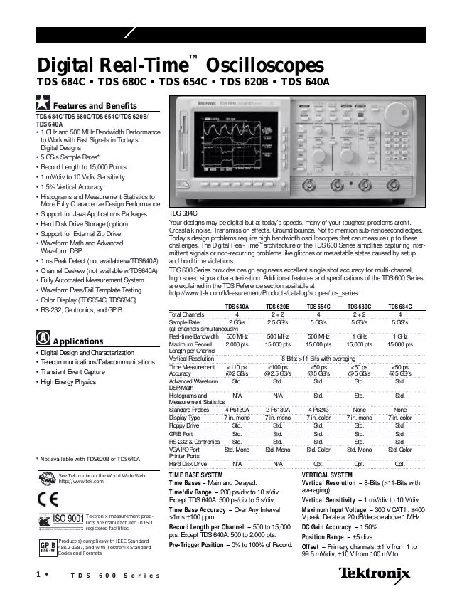
• A maximum digitizing rate of 2 GS/s on each of the
full-featured channels (four on the TDS 640A and 644A, two on the TDS 620A)
simultaneously with an analog bandwidth of 500 MHz.
• Four input channels, each with 8-bit vertical resolution,
and each with a record length of 2,000 samples and 8-bit vertical resolution.
• Extensive triggering capabilities: such as edge, logic, and
glitch. Video trigger (Option 05) is also available. The video trigger
modes are NTSC, SECAM, PAL, HDTV, and FlexFormatTM (user definable format).
• Acquisition modes such as sample, envelope, and average.
• A full complement of advanced functions, like continuously-updated
measurements, results and local pass/fail decision making.
• Specialized display modes, such as variable persistence
with color grading, dot or vector mode, sin(x)/x or linear display
filters, and user selectable color pallettes. The "Fit to Screen" features
compresses the entire waveform record to fit on the screen.
• A unique graphical user interface (GUI), an on-board help
mode, and a logical front-panel layout which combine to deliver a new
standard in usability.
• Full GPIB software programmability. Hardcopy output using GPIB,
RS-232, or Centronics ports. RS-232 and Centronics are
standard on the TDS 644A and optional, as option 13, on the TDS 620A and
640A.
• VGA output for driving remote monitors.
• A 1.44 Mbyte, DOS 3.3 or later-compatible, floppy disk
drive (option 1F on the TDS 620A and 640A) and NVRAM mass storage for saving waveforms, hardcopies, and oscilloscope setups.
• On the TDS 644A, a color display for distinguishing among waveforms,
their measurements, and associated text.
User Interface
Use a combination of front-panel buttons, knobs, and
on-screen menus to control the oscilloscope's many functions. The front-panel controls are grouped according to function: vertical, horizontal,
trigger, and special. Set a function you adjust often, such as vertical positioning or the time base setting, directly by its own front-panel knob. Set functions which you change less often, such as vertical coupling and horizontal mode, indirectly using selected menus.
Menus
Pressing one (sometimes two) front-panel button(s), such as
vertical menu, displays a main menu of related functions, such as coupling,
bandwidth, etc., at the bottom of the screen. Pressing a main-menu
button, such as coupling, displays a side menu of settings for that
function, such as AC, DC, or GND (ground) coupling, at the right side of the screen. Pressing a side-menu button selects a setting such as DC.
Indicators
On-screen readouts help you keep track of the settings for various functions,
such as vertical and horizontal scale and trigger level.
Some readouts use the cursors or the automatic parameter extraction feature (called measure) to display the results of measurements made or the status of the instrument.
General Purpose Knob
Assign the general purpose knob to adjust a selected parameter function.
More quickly change parameters by toggling the SHIFT button.
Use the same method as for selecting a function, except the final
side-menu selection assigns the general purpose knob to adjust some
function, such as the position of measurement cursors on screen, or the setting for a channel's fine gain.
GUI
The user interface also makes use of a GUI, or Graphical
User Interface, to make setting functions and interpreting the display more
intuitive. Some menus and status are displayed using iconic representations
of function settings such as those shown here for full, 100 MHz, and 20
MHz bandwidth. Such icons allow you to more readily determine status
or the available settings.
4 Manuals
User manual
Manual type:
User manual
Pages:
378
Size:
2.0 MB
Language:
english
Revision:
Seventh edition
Manual-ID:
070-8709-06
Date:
Quality:
Electronic document, no scan, very well readable.
Upload date:
April 28, 2013
MD5:
95d81bae-a023-aa2e-8c63-a91e8335a437
Downloads:
6694
Service manual
Manual type:
Service manual

Pages:
288
Size:
106.3 MB
Language:
english
Revision:
Manual-ID:
070-8718-04
Date:
January 1993
Quality:
Electronic document, no scan, very well readable.
Upload date:
Dec. 25, 2017
MD5:
cef247aa-4071-c11f-8501-35210be2fa0f
Downloads:
1772
Datasheet
Manual type:
Datasheet
Pages:
2
Size:
45.3 KB
Language:
english
Revision:
Manual-ID:
55W-10066-6
Date:
January 1998
Quality:
Electronic document, no scan, very well readable.
Upload date:
Dec. 28, 2017
MD5:
49412666-0c8c-6fdf-0e80-d713016d8139
Downloads:
1751
Service manual
Manual type:
Service manual
Pages:
288
Size:
5.0 MB
Language:
english
Revision:
Manual-ID:
070-8718-04
Date:
January 1993
Quality:
Electronic document, no scan, very well readable.
Upload date:
Sept. 15, 2019
MD5:
b540c661-d244-d59a-2c1e-59d9320afc70
Downloads:
731