Yaesu - FT-900 - Transceiver
Manufacturer:
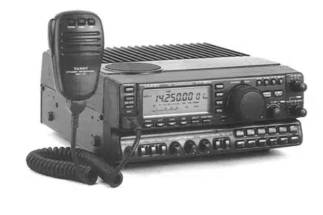
Image 1 of 3
If you have any other photos or manuals for the
Yaesu FT-900
you can
upload the files here.
Equipment:
FT-900
Date:
1994
Category:
Group:
Sub Group:
Information
Your FT-900 is a high-performance transceiver providing up to 100 watts transmitter output power on all HF amateur radio bands in CW, SSB and FM modes, and up to 25 watts carrier in AM. The receiver tunes all frequencies between 100 kHz and 30 MHz in 2.5-Hz steps.
For mobile operation, a new lightweight detachable sub-panel permits separating the transceiver and mounting the rear main unit in a remote location, keeping the most-commonly used front panel controls and display where you need them-in a comfortable, safe location (YSK-900 Separation Kit required for separate installation). This makes the FT-900 convenient for mobile and maritime amateur operation, or wherever space is critical.
Operating frequency and other important settings are displayed on a high-contrast backlit LCD. The new three-mode bargraph meter display features delayed “peak hold” circuitry for the tuning bargraph segments that simplifies tuning stations with rapidly varying signal strength. The new flexible mounting scheme combined with the famous high-performance circuitry of the earlier FT-890 is combined to form a compact, reliable rig that is ideally suited for base or mobile operation.
CW enthusiasts will enjoy the new CW reverse-sideband, which lets you switch the receiver carrier point (offset) to help sidestep QRM, and not have toretune stations when switching between LSB and CW (convenient when working on 40 meters and below). If you use a multi-mode TNC or CW decoder, the adjustable BFO offset lets you match the CW pitch to that used by your unit so that the tuned station will be centered in the receiver IF passband, and your decoder will give optimum copy. The FT-900 full-featured internal electronic keyer allows front panel control of keying speed, weighting and mode (semi-/full break-in).
Modern circuit design employs surface-mount components on composite epoxy boards for high reliability and serviceability. Twin direct-digital synthesizers (DDSs) and a magnetic rotary encoder with selectable 2.5-, 5- or 10-Hz tuning steps provide silent, silky-smooth tuning, pure local signals and very fast tx/rx changeover important when operating QSK CW. Frequency accuracy and stability are assured by driving both DDSs from a single master oscillator, and the optional TCXO-3 temperature-compensated crystal oscillator is available for enhanced ±2-ppm stability from 0° ~ +50° C.
The low-noise, high performance receiver front end uses parallel high-IDSS FETs in a constant-gain, grounded-gate RF amplifier, feeding an active double balanced quad FET-ring mixer. The RF amplifier can be bypassed for direct-feed to the mixer (by the IPO button), and a 12-dB attenuator can be inserted for clear copy of even very strong signals.
Interference rejection is facilitated by the unique "up-down" conversion scheme, and includes an IF shift and notch circuit. The optional XF-110S crystal filter can be installed for enhanced SSB and AM nar-row-skirt selectivity.
Four microprocessors in the FT-900 are programmed to provide the simplest possible control interface for the operator. Two independent (A/B) VFOs for each band (20 total) hold their own frequencies and modes settings. One hundred memories store all of this data for both VFOs, giving a total of 220 independent sets of frequency, mode and other selections.
Flexible scanning features allow all 100 memories or only those selected to be freely-tuned and scanned. In addition, ten special memories also let you limit the tuning/scanning range between their stored frequencies. Scan resume mode is selectable between timed or carrier-delay, and scanning speed is also adjustable.
Other valuable features include an effective noise blanker, all-mode squelch, multi-function meter, and an AF speech processor with adjustable IF offset which lets you increase the average power of your SSB signal and allows tailoring audio response to your voice characteristics. The FT-900 weighs under 5.5 kg and an internal thermally-switched fan allows full transmitter output without any rear panel protrusions, giving easy access to rear panel controls and connectors.
A choice of automatic antenna tuners is available for the FT-900, each with its own microprocessor and 31 memories which store most recent antenna matching settings for nearly instant recall while changing operating frequency. The ATU-2 can be mounted inside the transceiver, while the FC-800 can be installed remotely at the antenna feedpoint. Each antenna tuner is controlled from the front panel of the FT-900.
The MH-31a8J hand microphone is supplied with FT-900. Other accessories include the FP-800 AC Power Supply with Loudspeaker; the SP-6 External Loudspeaker with audio filters and optional LL-5 Phone Patch and the MMB-20 Mobile Mounting Bracket.
Before connecting the power cord, you should read the Installation section carefully, heeding the warnings in that section to avoid damage to the set. After installation, please take time to work through the Operation chapter, referring to the fold-out panel diagrams at the back of the manual as necessary for details. This manual is intended to be read while sitting down in front of the FT-900, so you can try out each control and feature as they are described.
3 Manuals
Service manual
Manual type:
Service manual
Pages:
173
Size:
27.5 MB
Language:
english
Revision:
Manual-ID:
Date:
Quality:
Scanned document, all readable.
Upload date:
July 27, 2014
MD5:
1fd0c23b-4b3d-68a4-1412-99402f495c92
Downloads:
2766
User manual
Manual type:
User manual
Pages:
51
Size:
3.4 MB
Language:
french
Revision:
Manual-ID:
Date:
Quality:
Scanned document, reading partly badly, partly not readable.
Upload date:
Jan. 11, 2020
MD5:
5e2d42ab-9d5d-1ec2-e651-95e31adb8c5c
Uploader:
Le Corre
Downloads:
321
User manual
Manual type:
User manual
Pages:
73
Size:
9.3 MB
Language:
english
Revision:
Manual-ID:
Date:
January 1994
Quality:
Scanned document, all readable.
Upload date:
March 16, 2020
MD5:
65df5dee-7d31-7807-2934-0bb58f0a5103
Uploader:
willem
Downloads:
299