JBL - 6020 - Amplifier
Manufacturer:

Image 1 of 1
If you have any other photos or manuals for the
JBL 6020
you can
upload the files here.
Equipment:
6020
Date:
1977
Category:
Group:
Sub Group:
Information
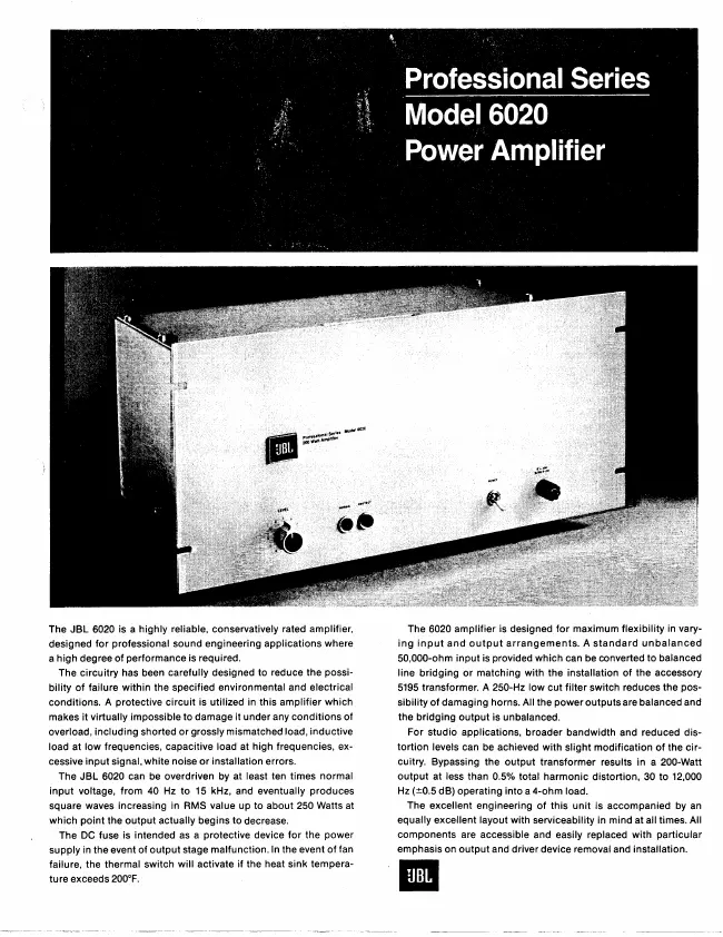
The JBL 6020 is a highly reliable, conservatively rated
amplifier, designed for professional sound engineering
applications where a high degree of performance is required.
The circuitry has been carefully designed to reduce the
possibility of failure within the specified environmental
and electrical conditions. A protective circuit is utilized
in this amplifier which makes it virtually impossible to
damage it under any conditions of overload, including
shorted or grossly mismatched load, inductive load at low
frequencies, capacitive load at high frequencies, excessive
input signal, white noise or installation errors.
The JBL 6020 can be overdriven by at least ten times normal
input voltage, from 40 Hz to 15 kHz, and eventually produces
square waves increasing in RMS value up to about 250 Watts
at which point the output actually begins to decrease.
The DC fuse is intended as a protective device for the power
supply in the event of output stage malfunction. In the
event of fan failure, the thermal switch will activate if
the heat sink temperature exceeds 200°F.
The 6020 amplifier is designed for maximum flexibility in
varying input and output arrangements. A standard unbalanced
50,000-ohm input is provided which can be converted to
balanced line bridging or matching with the installation of
the accessory 5195 transformer. A 250-Hz low cut filter
switch reduces the possibility of damaging horns. All the
power outputs are balanced and the bridging output is
unbalanced.
For studio applications, broader bandwidth and reduced
distortion levels can be achieved with slight modification
of the circuitry. Bypassing the output transformer results
in a 200-Watt output at less than 0.5% total harmonic
distortion, 30 to 12,000 Hz (±0.5 dB) operating into a 4-ohm
load.
The excellent engineering of this unit is accompanied by an
equally excellent layout with serviceability in mind at all
times. All components are accessible and easily replaced
with particular emphasis on output and driver device removal
and installation.
1 Manual
Schematics diagram
Manual type:
Schematics diagram
Pages:
3
Size:
1.5 MB
Language:
english
Revision:
Manual-ID:
Date:
January 1977
Quality:
Scanned document, all readable.
Upload date:
Sept. 25, 2017
MD5:
b0137cf1-e31d-c88d-ba50-293824654f80
Downloads:
1332