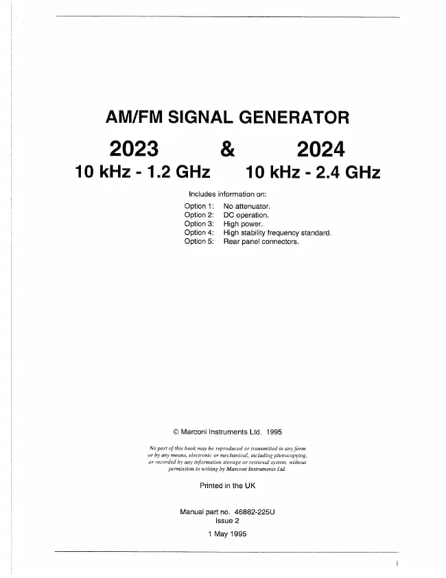
Marconi - 2023 - Generator
Manufacturer:
No picture available!
Maybe you can
upload a pic
for the
Marconi 2023 ?
If you have any other manuals for the
Marconi 2023
you can
upload the files here.
.
Equipment:
2023
Date:
1995
Category:
Group:
Sub Group:
Information
Introduction
The 2023 and 2024 are portable and lightweight synthesized signal
generators covering the frequency range 10 kHz to 1.2 GHz (2023) and 10
kHz to 2.4 GHz (2024). A dot matrix display with a comprehensive set of utility
menus allow flexibility of operation and ease of use. The RF output can be
amplitude, frequency, phase or pulse modulated. An internal programmable
AF source is capable of generating simultaneous two-tone modulation.
All parameters can be entered from a front panel keyboard and a rotary
control can be used to adjust most settings. Microprocessor control ensures
that the instruments are flexible and easy to use and allows programming by
either the General Purpose Interface Bus (GPIB) or by RS-232. The GPIB is
designed to IEEE Standard 488.2. The interfaces allow remote control of all
functions except the supply switch, and allow the instruments to be used
either manually or as part of a fully automated test system.
Main features
Operation
Selection of parameters on the screen may involve one or more of the
numeric, hard or menu selection keys or the rotary control knob. Parameters
may be set to specific values by numeric key entry, while values may be
varied in steps of any size using the DOWN/UP keys or altered by moving the
control knob, set to a particular sensitivity.
Display
The display is a dot matrix liquid crystal panel, with backlighting. Display
contrast may be varied to accommodate differing lighting conditions and the
setting saved in memory. A graphical display test is available to the user.
Frequency selection
Carrier frequency is either selected directly via the keyboard or remotely via
the interfaces. Frequency resolution is 1 Hz across the band* A series of
carrier frequencies can be stored in non-volatile memory for recall when
required.
Output
RF output up to +13 dBm can be set by direct keyboard entry with a resolution
of 0.1 dB over the entire range. For instruments fitted with the high power
option, RF' output is increased to +25 dBm (+19 dBm above 1.2 GHz). A
carrier ON/OFF key is provided to completely disable the output.
A choice of level units is available to the user and provision is made for the
conversion of units (for example, dBm to ¡aV) by a simple keypress.
An electronic trip protects the generator output against reverse power of up
to 50 W. This prevents damage to output circuits when RF or DC power is
accidentally applied to the RF OUTPUT connector.
To facilitate testing of receiver squelch systems, an attenuator hold function
allows control of the RF output without introducing RF level drop-outs from the
step attenuator.
Modulation
Comprehensive amplitude, frequency and phase modulations are available.
Pulse modulation can be applied to the carrier from an external pulse source.
The instrument also accepts one or two logic level inputs to produce a 2-level
or 4-level FSK modulated output. An internal modulation oscillator is provided,
having a frequency range of 0.01 Hz to 20 kHz. The oscillator is capable of
generating one or two modulation tones simultaneously in one modulation
channel An independent BNC input on the front panel allows external
modulation signals to be combined
with the internal signal(s). These sources can be combined to give a number
of modulation modes. The pulse modulation can be used in combination with
the other forms of modulation.
The frequency modulation range provides a Î dB bandwidth of typically 100
kHz and provides FM deviation up to a maximum of 100 kHz. AC or DC
coupled FM can be selected. Phase modulation is also available with a 10 kHz
bandwidth up to a maximum of 10 radians.
Amplitude modulation with a 1 dB bandwidth of typically 30 kHz and with
modulation depths of up to 99.9% is available with a resolution of 0.1%. Pulse
modulation is available as standard with typical rise and fall times of less than
10 |is and 40 dB on/off ratio.
The external input voltage required for 100% modulation is I V RMS (1.414 V
peak). To accommodate other signal levels, Automatic Level Control (ALC)
can be selected which provides correctly calibrated modulation for inputs
between 0.75 and 1.25 V RMS.
A MOD ON/OFF key simplifies the testing of signal to noise ratio.
Incrementing
All major parameters can be incremented or decremented in step sizes
entered via keyboard entry or remotely. If no step size is entered for a
parameter, the steps are preset to I kHz for carrier frequency, 1 kHz for
modulation oscillator, 1 kHz for FM deviation, 0.1% for AM depth, 0.01 rad for
$M and 1 dB for output level.
In addition, the rotary control knob can be used to vary the parameter with
the sensitivity of the knob being changed by means of the xlO and -*-10 keys.
Frequency sweep
The sweep capability of the instrument allows comprehensive testing of
systems. Four parameters are used to specify sweep; start, stop, step size
and time per step, all of which may be specified by the user. The sweep can
be paused at any time. During the sweep the RF level can be altered using the
rotary control. Sweep triggering can be single shot or continuous and can be
initiated directly or on the detection of a trigger. The triggering signal may
either be programmed or from a TTL signal applied to the rear panel
TRIGGER input.
Memory
The instrument provides both non-volatile and volatile memory for storing
instrument settings. The non-volatile memory provides 100 instrument
settings and 100 settings of carrier frequency only. The volatile memory
(RAM) also provides 100 instrument settings. Any one of the nonvolatile
instrument settings can be selected as the power-up setting for the
instrument.
Memory cloning
The stored settings in one instrument can be easily transferred (without the
use of a controller) to another instrument using the RS-232 interface, or to
several other instruments using the GPIB interface.
Memory sequencing
A software facility allows sequences of stored instrument settings to be
defined. The incrementing facilities can then be used to cycle through the
settings in manually operated test systems.
Programming
A GPIB interface is fitted so that all functions are controllable via the interface
bus which is designed to the IEEE Standard 488.2. The instrument can
function both as talker and listener. The instrument also has an RS-232
interface which uses the common GPIB command set. The interfaces enable
the instrument to be remotely controlled as well as being used to transfer
settings (cloning) from one instrument to another.
Software protection
To prevent accidental interference with the contents of internal memories,
internal data is protected.
Calibration data
All alignment data is digitally derived. Realignment can be undertaken,
without removing covers, by protected front panel functions or via the GPIB
interface.
Spectral purity
With an SSB phase noise performance of typically -121 dBc/Hz at 20 kHz
offset from a 1 GHz carrier, these instruments can be used for both in-
channel and adjacent channel receiver measurements. Harmonically related
signals and non-harmonics are typically better than -25 dBc and -60 dBc
respectively.
Calibration
This instrument has a recommended two year calibration interval after which
it should be returned for recalibration (for addresses refer to 'Addresses'
section at end of manual).
1 Manual
User manual
Manual type:
User manual
Pages:
204
Size:
7.6 MB
Language:
english
Revision:
2
Manual-ID:
46882-225U
Date:
May 1995
Quality:
Scanned document, all readable.
Upload date:
Jan. 6, 2019
MD5:
b54fb622-e7fd-2dd0-e28a-66fb2a3079d3
Downloads:
1061